PSCAD™ tappy
Last updated: 8 October 2026
Version: v1
Software required:
Background
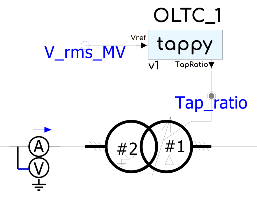
tappy is a PSCAD™ Definition provided with the gridmo software platform. It wraps the standard MHI OLTC block, which is used to represent the On Load Tap Changer (OLTC) that regulates the tap ratio of a transformer.
The underlying operation of the MHI OLTC block has not been changed. gridmo has added a wrapper around this block to enable engineers to do the following:
- Fast tapping of the OLTC during the initialization period, including resetting the integrator when the fast tapping interval ends.
- Receive initial tap position from external static solutions (e.g. PSS®E or PowerFactory).
Adding tappy into a model
Step 1: Add tappy to your PSCAD™ Workspace
Add the tappy block into your PSCAD™ Workspace by the same process as adding the smiby block:
- Download the latest version of tappy using the
DOWNLOAD MODELbutton above. - Open your PSCAD™ Workspace file from your gridmo Engine's Inputs folder (
.pswx) in PSCAD™. - Right click on the
Definitionsfolder underneath the PSCAD™ Case in the Workspace view and selectImport From File. - Navigate to the location of the tappy definition file (
.psdx) and select it. - Right click on the
tappydefinition (it will appear at the bottom of the list of definitions) and selectCopy. - Right click in the whitespace area in your Workspace and select
Paste. - Connect the necessary signals to the tappy block:
input: Regulated winding RMS voltage [p.u.]output: Tap ratio [p.u.]
You can have multiple tappy blocks in your PSCAD™ Workspace to regulate the tap ratios of different transformers.
Step 2: Configure tappy parameters
To configure the tappy block, right click on the tappy block and navigate to 'Edit Parameters'. The tappy block has the following categories of parameters:
- Main settings
- OLTC settings
- Fast tapping
- Static initialization
- Advanced
Main settings
Name- Distinguishes between multiple tappy blocks in a PSCAD™ workspace and when using the OUTPUT, LOCATION= Command. Set to a unique name such as
OLTC_1orOLTC_2.
- Distinguishes between multiple tappy blocks in a PSCAD™ workspace and when using the OUTPUT, LOCATION= Command. Set to a unique name such as
Mode for finding initial tap positionPSSE/PowerFactory Static— Initial tap position is provided by a static solution (e.g. PSS®E or PowerFactory).Self-initialize— Initial tap position is found by the tappy block itself.
Taps locked after initialization?Yes— Tap position is locked after initialization and will not change.No— Tap position remains unlocked after initialization and can change.
OLTC settings
Which winding is controlled - is it the tapped winding?Yes— The tapped winding is controlled.No— The non-tapped winding is controlled. (Default)
The tapped winding is generally the high voltage winding of the transformer, and the controlled winding is generally the medium voltage winding. Therefore, this is typically set to 'No'.
Voltage setpoint [p.u.]- Target voltage of the regulated winding. This defaults to 1.00 p.u.
Tap step size [p.u.]- Voltage change per tap, as a fraction of the nominal voltage. This defaults to 0.0125 p.u.
Nominal voltage [kV]- Nominal voltage of the regulated winding.
Tap delay during normal operation [s]- Time delay after a tap change before the next tap change can be initiated.
Nominal tap position- Nominal tap position of the tapped winding. This defaults to 11.
(ADD 1 EXTRA) Number of taps increasing from nominal position- Number of available tap positions above the nominal position. This defaults to 11.
There is a bug in the MHI OLTC block that stops the final tap position from being used. Please enter 1 extra tap position here otherwise your OLTC will not be capable of reaching maximum tap position, it will stop at the second to last tap position.
Number of taps decreasing from nominal position (not including your final tap position).- Number of available tap positions below the nominal position. This defaults to 10.
Hysteresis band based on step of one tap [p.u.]- Hysteresis band for the tap changer, set to deadband ÷ tap step size. For example, if the deadband is ±0.01 p.u. and the tap step size is 0.0125 p.u., set this to
0.8 = 0.01 / 0.0125. This defaults to 0.8.
- Hysteresis band for the tap changer, set to deadband ÷ tap step size. For example, if the deadband is ±0.01 p.u. and the tap step size is 0.0125 p.u., set this to
Fast tapping
These settings are only used if the Mode for finding initial tap position is set to Self-initialize.
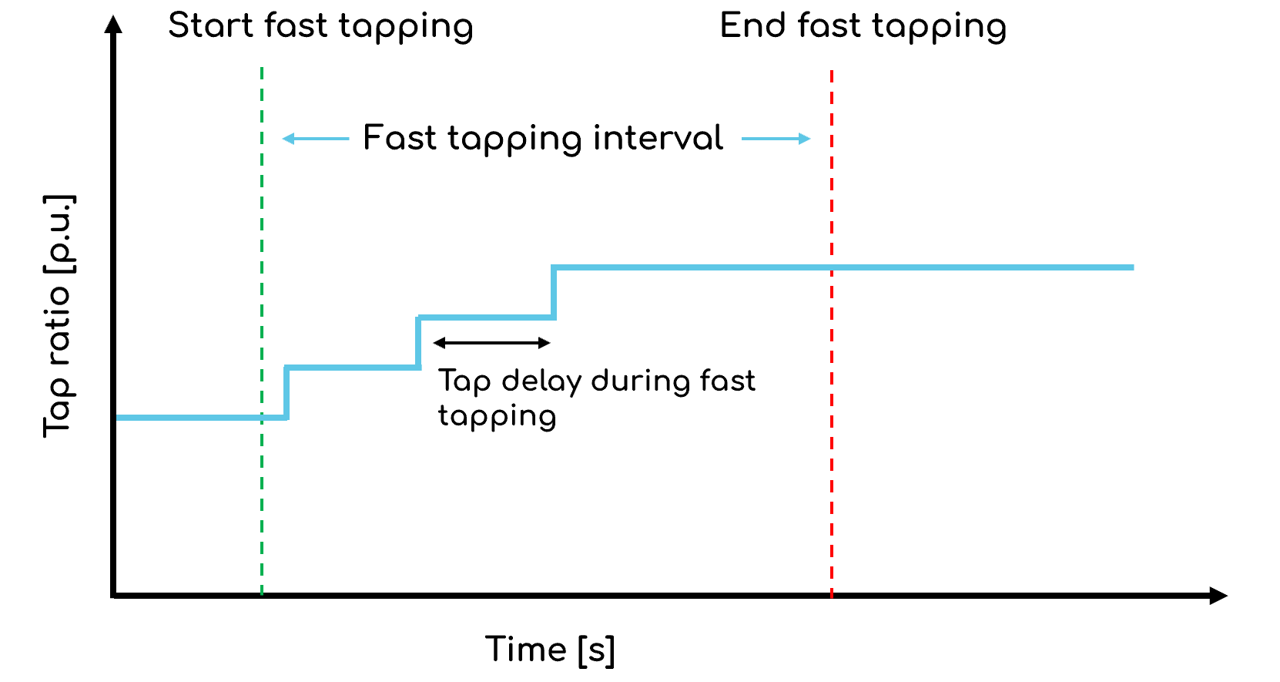
Start fast tapping [s]- Beginning of the fast tapping interval. This defaults to 0.2 seconds.
End fast tapping [s]- End of the fast tapping interval. This defaults to 2.5 seconds.
Tap delay during fast tapping [s]- Time between tap changes during the fast tapping interval. This defaults to 0.1 seconds.
Static initialization
These settings are only used if the Mode for finding initial tap position is set to PSSE/PowerFactory Static.
Tap ratio from static [p.u.]- The tap ratio from the static solution is written to this field in the gridmo Global Variable
$pscad_initialization.
- The tap ratio from the static solution is written to this field in the gridmo Global Variable
Advanced
Vrms filter time constant [s]- Time constant for calculating the RMS voltage. This defaults to 0.05 seconds.
Direction of tap changing+1— Tap changes in the positive direction (default).-1— Tap changes in the negative direction.
Using tappy's metering channels
The tappy block has several built-in output channels which can be used. Replace LOCATION= with the name of the tappy block you have set in the previous step.
Voltages
// Voltage setpoint [p.u.]
OUTPUT, LOCATION=<enter_tappy_name_here>, TITLE=tap_voltage_set, VAL=V, NAME=i_put_name_here

// Regulated winding RMS voltage [p.u.]
OUTPUT, LOCATION=<enter_tappy_name_here>, TITLE=Vinput_pu, VAL=V, NAME=i_put_name_here
Tap
// Tap ratio [p.u.]
OUTPUT, LOCATION=<enter_tappy_name_here>, TITLE=tap_ratio, VAL=TAPRATIO, NAME=i_put_name_here

// Starting tap position
OUTPUT, LOCATION=<enter_tappy_name_here>, TITLE=starting_tap_position, NAME=i_put_name_here

// Tap enable flag
OUTPUT, LOCATION=<enter_tappy_name_here>, TITLE=tap_enab, VAL=BINARY, NAME=i_put_name_here

// Tap delay [s]
OUTPUT, LOCATION=<enter_tappy_name_here>, TITLE=tap_delay, NAME=i_put_name_here
Other
// Nominal voltage [kV]
OUTPUT, LOCATION=<enter_tappy_name_here>, TITLE=nominal_voltage, NAME=i_put_name_here
Updating tappy to a new version
Update the tappy block to the newest version by the same process as updating the smiby block:
- Download the latest version of tappy.
- In PSCAD, navigate to your project containing the tappy block(s) using the left hand sidebar, and expand 'Definitions' using the '+' symbol. Ensure that your current definition of the tappy block is named 'tappy' and not 'tappy_1' or otherwise.
- Right click on 'Definitions', click 'Import from File' and select the 'tappy_pscadv5.psdx' file you just downloaded. The new tappy definition should appear as 'tappy_1' in the project definitions.
- Open the scripts tab of PSCAD by navigating to the 'View' tab, select 'Panes' and then 'Scripts'.
- In the Scripts tab, click 'New' and navigate to the directory where the new tappy version was downloaded. Select and open the 'gridmo_update_tappy.py' script.
- Click 'Run' to update the tappy block to the new version. Note that the script will automatically transfer all your project settings from the existing tappy block.
- To complete the update, delete the old tappy definition and rename the new definition to 'tappy'.
Updating tappy may overwrite any of your custom modifications to tappy. In general, we recommend not making any changes to the tappy block or OEM libraries so that newer versions may be accommodated easily. If there is additional functionality you are looking for, please reach out to us.
Benchmarking the tappy block against PSS®E and PowerFactory OLTC models
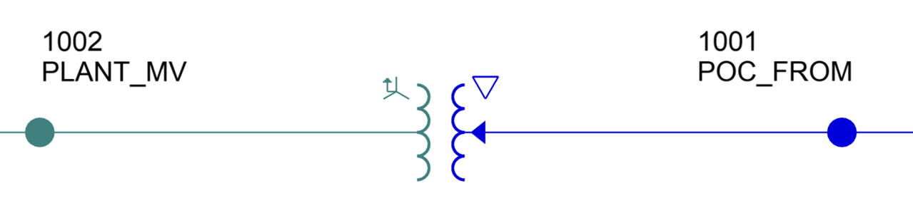
The details below provide an example of benchmarking the tappy block against the default PSS®E and PowerFactory OLTC models. In this example, the WECC Solar model is used. The diagram below provides an overview of the OLTC in the WECC Solar model.
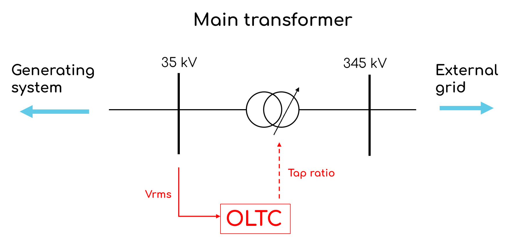
The tapped winding is the higher voltage winding (345 kV); however, the voltage is regulated on the medium voltage winding (35 kV). The OLTC reads the voltage of the medium voltage bus and compares it to the target voltage. If the voltage is too high, the OLTC will tap up. If the voltage is too low, the OLTC will tap down.
The WECC Solar OLTC has the following settings:
- Tap step size: 1.25%
- Nominal tap position: 11
- Maximum tap position: 21
- Minimum tap position: 1
- Setpoint voltage: 1.00 p.u.
- Deadband: 0.01 p.u.
- Tap delay: 60 seconds
The following sections detail the relevant settings for the OLTC in the WECC Solar PSS®E and PowerFactory models.
PSS®E OLTC model
The diagram below shows the steady state settings for the OLTC in PSS®E. The key settings are highlighted in the diagram.
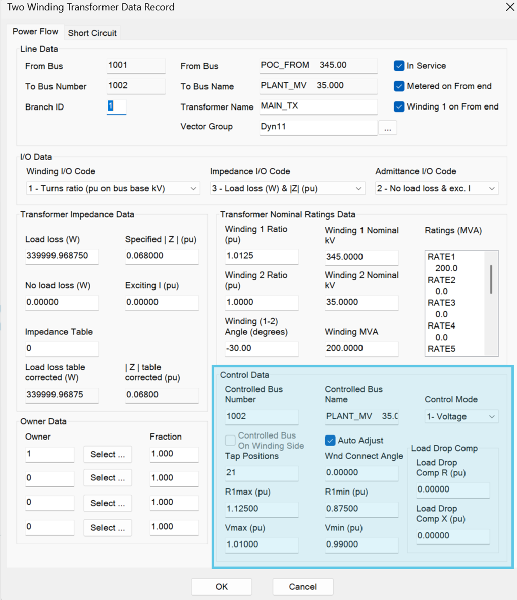
The WECC Solar model uses PSS®E's model OLTC1T to represent the OLTC on the main transformer (345/35 kV). For more information on the OLTC1T model, please refer to the PSS®E Model Library.
The following is the OLTC model in the WECC Solar .dyr file:
//      IBUS        'OLTC1T'        JBUS        ID      CON(J+1)    CON(J+2)    CON(J+3)
        1001        'OLTC1T'        1002        1       60          0.05            60/
| Parameter | Value | Description |
|---|---|---|
CON(J+1) | 60 | Td — time delay (seconds) |
CON(J+2) | 0.05 | Tc — time constant of tap changer (seconds) |
CON(J+3) | 60 | Tsd — time before subsequent tap signal sent (seconds) |
PowerFactory OLTC model
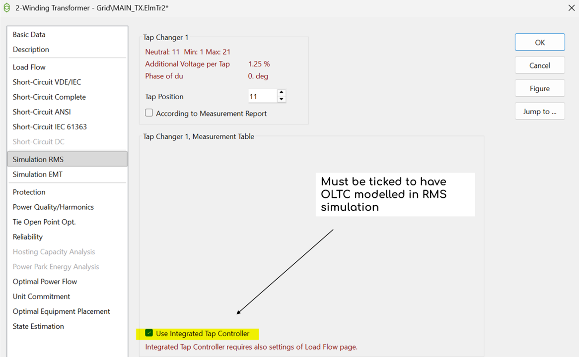
The diagram below shows how the OLTC is enabled in PowerFactory RMS simulations. If this box is not checked, the OLTC will not be enabled in the RMS simulation. For a more complex OLTC representation, a separate dynamic model must be defined.
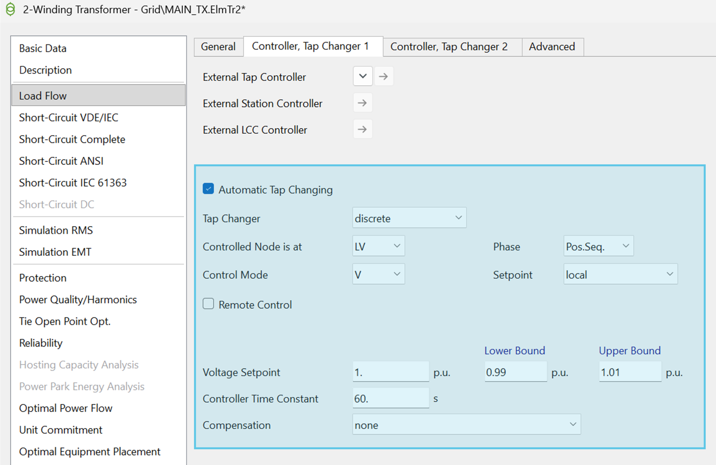
Note that the RMS representation of the OLTC uses the settings that are specified in the Load Flow tab of the transformer element. The key settings are highlighted in the diagram below.
Benchmark results
The interactive plot below shows the benchmarking of the PSCAD™ tappy block against the PSS®E and PowerFactory OLTC models represented in the WECC Solar model.
The tappy block benchmarks very well against the standard PSS®E and PowerFactory OLTC models. It is should be noted that there is a misalignment observed between PSS®E and PowerFactory/PSCAD™ OLTC models when the OLTC moves from increasing tap ratio to decreasing tap ratio. The PSS®E OLTC model will wait for the period of CON(J+1) before sending the next tap signal change whereas the PowerFactory/PSCAD™ OLTC model will send the next tap signal change immediately.
Revision history
Version 1 | 8 October 2026
- First release.