DIgSILENT PowerFactory Dynamic
Introduction
The PowerFactory Dynamic Node performs dynamic study simulations which are powered by PowerFactory, a 3rd party power systems software. It leverages the following PowerFactory modules:
- Base package
- Stability Analysis Functions (RMS)
This Node is typically used for the following:
- Completing dynamic studies (e.g. validating Generator Performance Standards).
- Benchmarking plant models (e.g. comparing the performance of PowerFactory and PSCAD™ plant models).
Check our system requirements page for information on which PowerFactory versions are currently supported.
User inputs
Select model
Model
Defines the input directory and file name of the PowerFactory project file, including the .pfd file extension. To use the PowerFactory project file (.pfd) from a linked PowerFactory Static Node, select Use model from linked PowerFactory Static Node.
Example:
sunny-solar-farm\SMIB.pfd
File paths are relative to the Engine's 'inputs' directory, as defined by the Engine configuration parameter dirs.inputs. For example, if dirs.inputs was set as C:\Users\johnsmith\gridmo\Inputs\:
| Absolute file path | Relative file path (required by gridmo) |
|---|---|
| C:\Users\johnsmith\gridmo\Inputs\sunny-solar-farm\SMIB.pfd | sunny-solar-farm\SMIB.pfd |
Study case
Defines the PowerFactory study case to activate when loading the project file. Study cases are identified by their folder hierarchy within the PowerFactory project, with each folder level separated by a backslash (\).
Example:
folder_1\folder_2\study_case
If no study case is specified, gridmo activates the currently active study case in the project. If no study case is active, gridmo activates the first study case found in the project.
When using a project file from a linked PowerFactory Static Node, the study case specified on that linked Node is used. The Study case field is hidden when Use model from linked PowerFactory Static Node is selected.
Study case paths must use backslashes (\) not forward slashes (/).
Dynamics user models
Defines the input directory of the PowerFactory dynamics user models.
Example:
sunny-solar-farm\dll-folder
All .dll files located in the specified folder will be loaded into PowerFactory. Ensure all .dll files in this folder are compatible with the PowerFactory version you are using. Selecting the inputs directory itself is not allowed.
Define simulation
Simulation time
Defines the duration of the dynamic study in seconds.
Example: Run a 30 second dynamic simulation.
30
The minimum simulation time is 0.1 seconds.
🔢 Supports mathematical operations.
Control Thévenin equivalent source
These controls allow you to define the behavior of the grid.
The grid is modelled as an infinite bus generator for SMIB studies. One of the following may be controlled in a Node:
- Voltage [p.u.]
- Frequency [Hz]
- Angle [degrees]
To use the SMIB control functionality, the PowerFactory project file must be configured as follows:
- The project file (
.pfd) has a single reference bus with a single AC Voltage Source (PowerFactory typeElmVac). - The project file (
.pfd) has a single line or series inductor between the slack bus and the plant model. This line represents the Thévenin equivalent source impedance.
gridmo will not automatically convert any existing reference bus generator / grid representation to an AC Voltage Source. You must manually change the slack bus generator to an AC Voltage Source in your PowerFactory project file.
If SMIB control functionality is enabled, any slack bus generator dynamic model will be replaced with a gridmo playback model to support interpolated voltage and frequency ramping.
Voltage
Defines the infinite bus generator voltage throughout the dynamic simulation. Enter a series of time [s], voltage [p.u.] pairs. The voltage is linearly interpolated between points. There are two methods for specifying the voltage - absolute and relative.
If your PowerFactory dynamic study uses a project file from a linked PowerFactory Static Node, it is often convenient to specify the voltage using the relative method, since it will utilise the infinite bus generator voltage solution from that specific project.
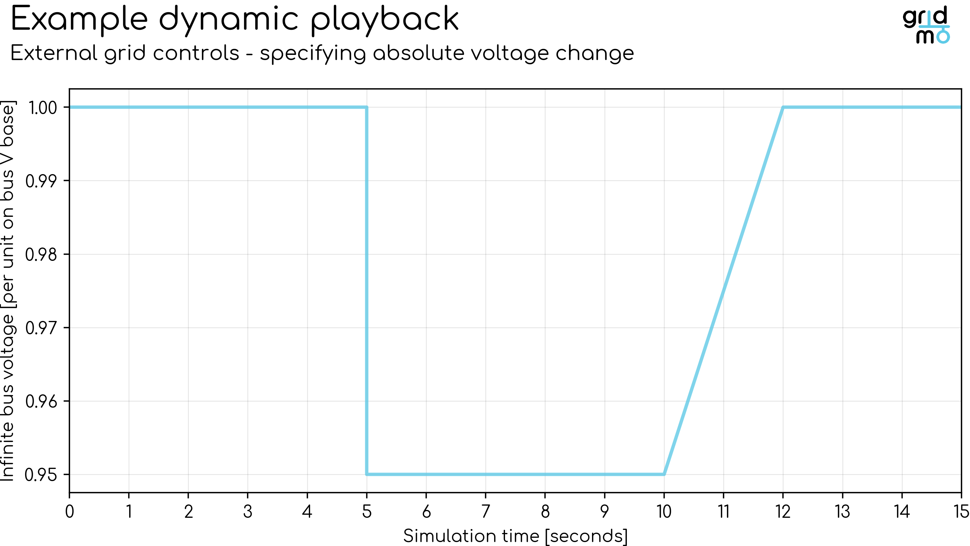
Specifying absolute voltage
Defines the infinite bus generator voltage throughout the dynamic simulation by specifying absolute voltage [p.u.].
Example: Perform a 15 second dynamic simulation. At 5 seconds, step the voltage from 1.00 [p.u.] to 0.95 [p.u.] in a single rapid step. At 10 seconds, ramp the voltage back up to 1.00 [p.u.] over 2 seconds.
Example
0,      1.00
4.9999, 1.00
5,      0.95
10,     0.95
12,     1.00
15,     1.00
Plot
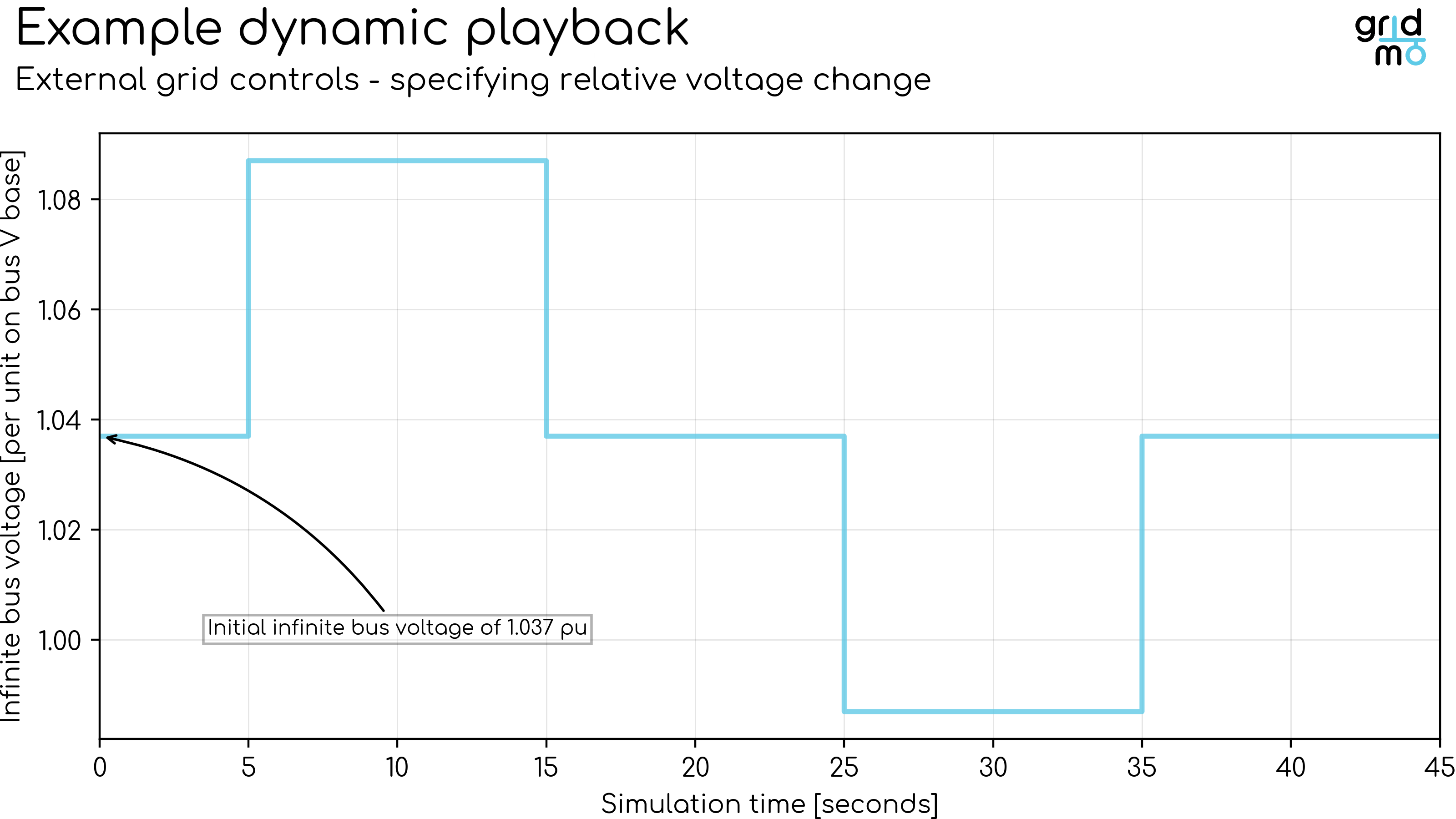
Specifying relative voltage
Defines the infinite bus generator voltage throughout the dynamic simulation by specifying relative voltage [pu]. The voltage change is relative to the voltage of the infinite bus generator voltage at the start of the dynamic simulation.
Example: Perform a 45 second dynamic simulation. At 5 seconds, step the voltage up 0.05 per unit (pu) in a single rapid step. At 15 seconds, step the voltage down to its initial value in a single rapid step. At 25 seconds, step the voltage down 0.05 per unit (pu) in a single rapid step. At 35 seconds, step the voltage up to its initial value in a single rapid step.
Example
0,      0 pu
4.999,  0 pu
5,      +0.05 pu
14.999, +0.05 pu
15,     0 pu
24.999, 0 pu
25,     -0.05 pu
34.999, -0.05 pu
35,     0 pu
45,     0 pu
Plot
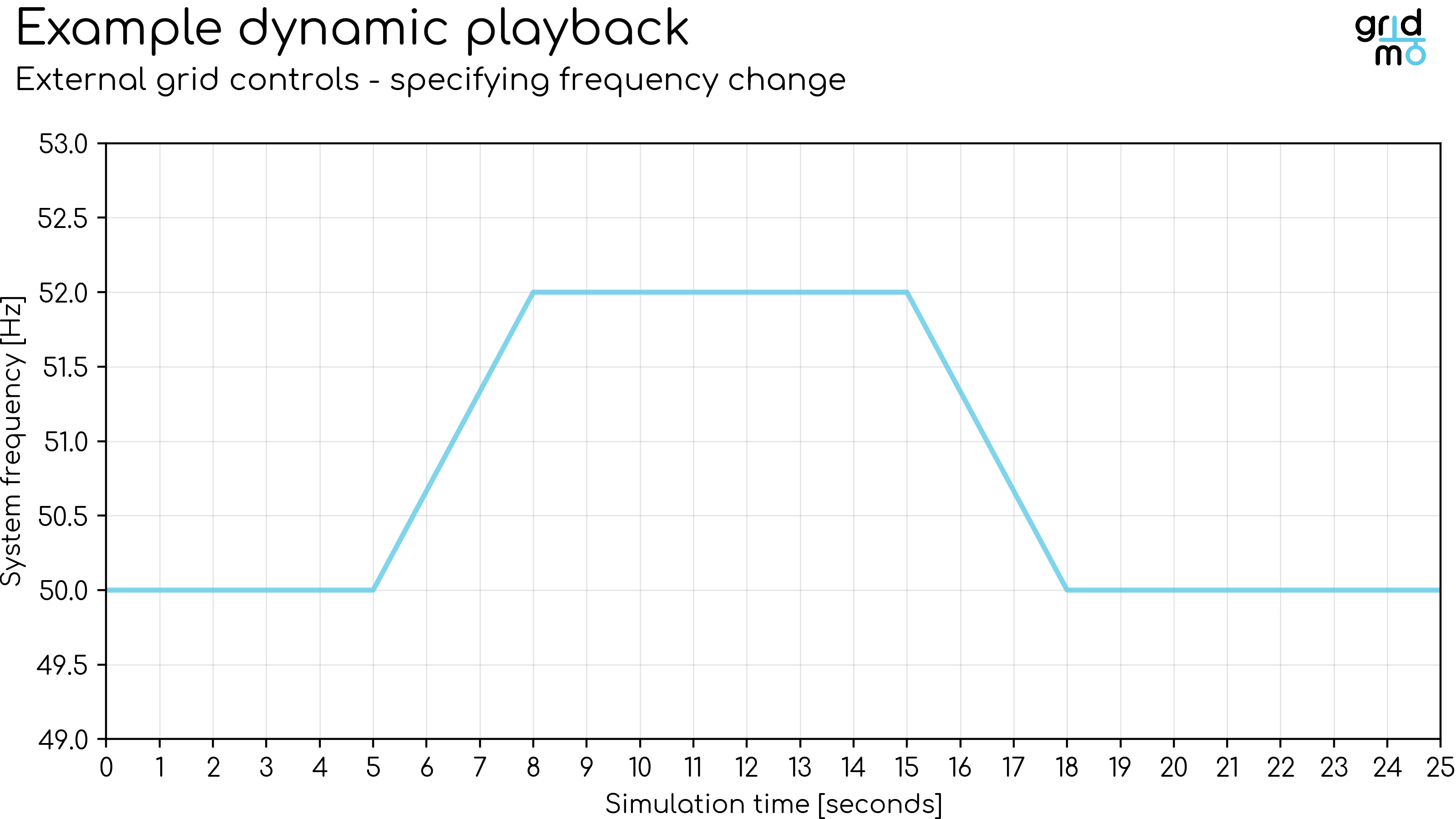
Frequency
Defines the infinite bus frequency throughout the dynamic simulation. Enter a series of time [s], frequency [Hz] pairs. The frequency is linearly interpolated between points.
Example: Perform a 25 second dynamic simulation. At 5 seconds, ramp the frequency up from 50.0 [Hz] to 52.0 [Hz] over 3 seconds. At 15 seconds, ramp the frequency back down to 50.0 [Hz] over 3 seconds.
Example
0,  50
5,  50
8,  52
15, 52
18, 50
25, 50
Plot
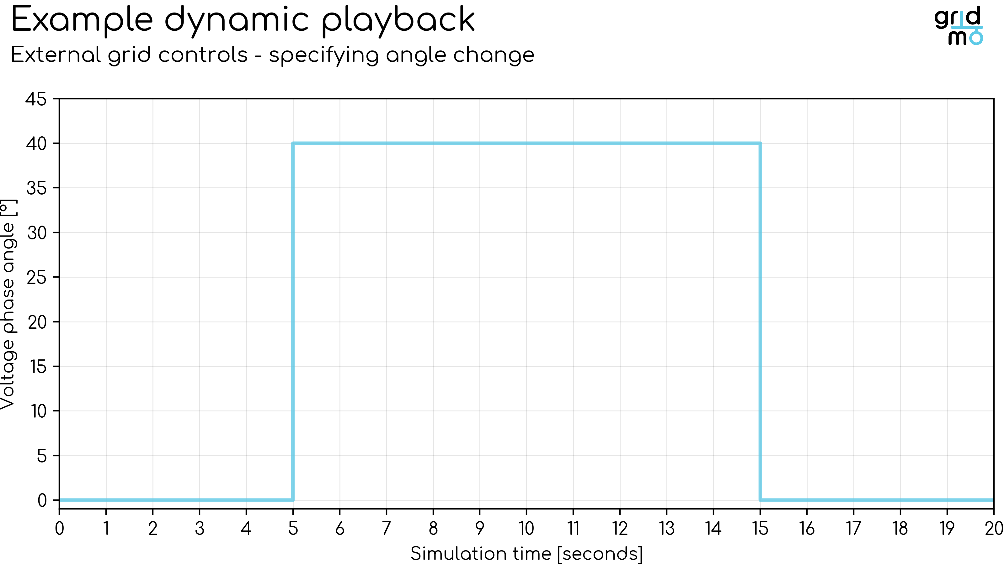
Angle
Defines the infinite bus voltage phase angle throughout the dynamic simulation. Enter a series of time [s], angle [degrees] pairs.
The voltage phase angle is not linearly interpolated between points - instead the angle is set to the absolute value at the time specified.
Voltage phase angle changes are instantaneous. Ramps are not supported.
Example: Perform a 20 second dynamic simulation. At 5 seconds, step the voltage phase angle from 0° to 40°. At 15 seconds, step the voltage phase angle back to 0°.
Example
0,  0
5,  40
15,  0
Plot
Actions
Defines the Commands which configure the dynamic simulation.
Supported Commands:
- SET: Sets the status of a network element.
- CONTROL: Controls a network element.
- SIMPLEFAULT: Applies a simple power system fault.
- BUS_FAULT: Applies a fault on a bus. The fault can be transient in nature, or result in protection operating to disconnect the bus.
- LINE_FAULT: Applies a fault on a transmission line. The fault can be transient in nature, or result in protection operating to disconnect the line, with optional auto reclose logic.
- VDISTURBANCE: Dynamically applies a relative over or under voltage disturbance using a fault or shunt (capacitor).
Specifying AT=0 will apply the Command at the very first time step once the dynamic simulation has been initialized.
Specifying AT=-1 will apply the Command once the dynamic data record has been loaded, but before the dynamic simulation has been initialized.
If you specify the value of the AT= argument beyond the simulation duration (e.g. simulation duration is 20 [s] and AT=25), the Command will not be applied and a warning will be raised.
Define outputs
Outputs
Defines the output channels of the dynamic simulation. The output channels defined here may be used later for plotting and/or further analysis.
Supported Commands:
- OUTPUT: Outputs a network element's dynamic simulation values as an Internode Variable.
By default, each OUTPUT records the full time series for the channel. You can optionally add AT= to store a single Internode Variable sampled from that series—either at a fixed time in seconds, at the start of the simulation using AT=SIM_START or at the end of the simulation using AT=SIM_END—see the OUTPUT Command reference below.
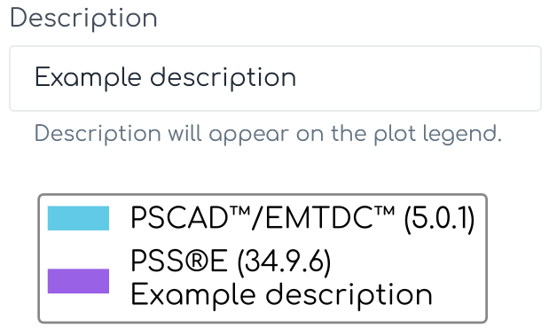
Outputs Description
Defines a short description of the dynamic simulation. This description will appear in the legend of any plot of the data generated by this Node.
Example:
Description here!
Advanced
PowerFactory version
Defines the PowerFactory version used for the Node. Defaults to Engine configuration.
gridmo Engine v1.5.0 onwards supports partial versions. See here for details.
Distance factor
Currently, gridmo only supports distance factor equal to 1 for PowerFactory Dynamic SMIB studies.
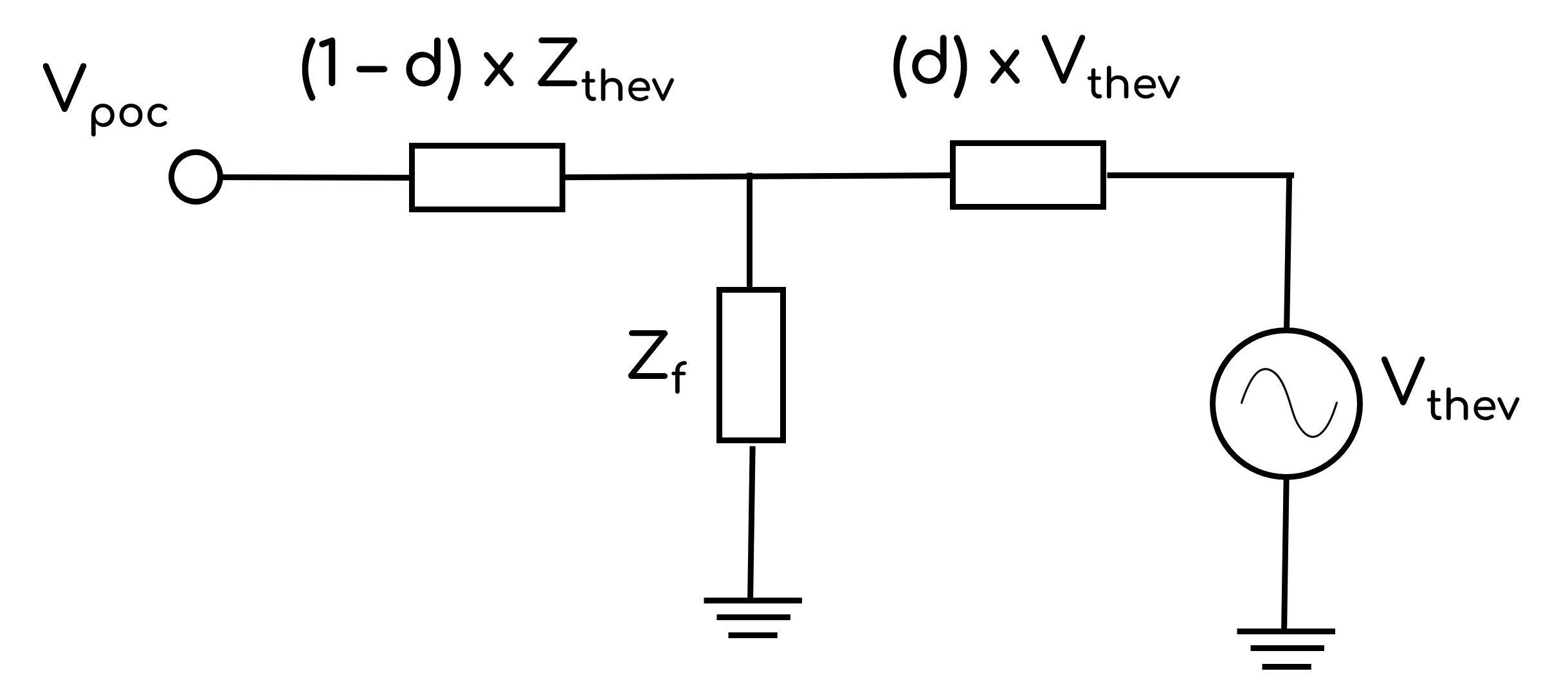
Defines the distance from the connection point at which disturbances are applied. Allowable values are between 0 and 1, where d=1 applies disturbances at the connection point. The image below shows a Thévenin equivalent of the grid as used in SMIB studies, commonly referred to as the 'infinite source', whereby:
- Vthev: Thévenin equivalent voltage source.
- Zthev: Thévenin equivalent impedance.
- Zf: Disturbance impedance.
- d: Distance factor.
- Vpoc: Connection point voltage prior to any disturbance.
Distance factor will apply to all relevant Commands in this Node such as:
SIMPLEFAULTVDISTURBANCE
Advanced Parameters
Advanced Parameters allow users to configure test details which are not commonly used. Advanced Parameters are often specific to each Node type.
Each line represents a new Advanced Parameter and is entered as a=b format, where a is the name of the Parameter and b is the corresponding value. All Advanced Parameters are set to their default values if they are not included in the Advanced Parameters field.
Example: Set Advanced Parameter, sample.parameter to a value of 5.
sample.parameter=5
API Reference
This section details the Commands and Advanced Parameters specific to the Node.
Lines in gridmo are defined using the following syntax: from_bus_name->to_bus_name#line_name. When completing SMIB studies, we recommend always having the to bus closer to your generator's connection point / the slack bus.
gridmo uses the PowerFactory Name field (loc_name) in conjunction with its PowerFactory type to find objects for several commands. These name fields are case sensitive. For example, if a bus is named Bus 1 in PowerFactory, it must be referenced as Bus 1 in gridmo. If the name is referenced as bus 1, gridmo will not be able to find the object.
If there are multiple objects with duplicate names, gridmo will apply the change to all objects. If you want to only control one object, we recommend using the PowerFactory Foreign Key field (for_name) FOREIGN_KEY= argument instead of the Name field (loc_name) to uniquely identify the object.
Spaces are supported in all gridmo argument fields.
SET Command
Set status
SET, OBJECT_NAME/FOREIGN_KEY=, AT=, STATUS=
Set the status (in or out of service) of the PowerFactory object specified by the OBJECT_NAME= or FOREIGN_KEY= arguments during a dynamic simulation.
- If the specified object is a circuit breaker or switch (PowerFactory class types
.ElmCoup,.ElmGndswtor.StaSwitch), this command applies an open or close command to the switch, rather than setting it in or out of service. This is achieved by creating anEvtSwitchevent object. - For all other objects (PowerFactory class types
*.Elm*,*.Rel*,*.Sta*or*.SetSelectexcluding those types mentioned above), this Command will set this asset to be in or out of service by toggling theOut of Servicecheckbox. This is achieved by creating anEvtOutageevent object.
Arguments:
- SET
- OBJECT_NAME or FOREIGN_KEY:
- OBJECT_NAME (
str): Name (loc_namefield) of the PowerFactory object to control. - FOREIGN_KEY (
str): Foreign key (for_namefield) of the PowerFactory object to control.
- OBJECT_NAME (
- AT 🔢 (
float): Time at which the Command is applied during the dynamic simulation [s]. UseAT=-1to set the variable before dynamic model initialisation. - STATUS (
str): Status of the object to set. Options:STATUS=IN: Object is set in-service, or if switch-like, is closed.STATUS=OUT: Object is set out of service, or if switch-like, is opened.
If your object is NOT switch like, such as a transformer or a generator, the SET, STATUS=OUT command can be used to set the object out of service during the simulation, however the SET, STATUS=IN command will not put the object back into service. This is a PowerFactory limitation.
If you want to turn a specified asset off and on within a dynamic simulation, you need to use switch-like objects like circuit breakers, switches or isolators
Example: At 2 seconds, take the object MainTransformer out of service.
SET, OBJECT_NAME=MainTransformer, AT=2, STATUS=OUT
Example: Open the bus-tie circuit breaker Bus Tie CB at 10 seconds and then reclose it at 20 seconds.
SET, OBJECT_NAME=Bus Tie CB, AT=10, STATUS=OUT
SET, OBJECT_NAME=Bus Tie CB, AT=20, STATUS=IN
Set transformer
SET, TX=, AT=, TAPRATIO=, WINDING=
Sets the tap ratio of a transformer.
Arguments:
- SET
- TX (
pas): Transformer definition. Transformers are defined using the following syntax:from_bus_name->to_bus_name#transformer_name(two-winding transformer) orfrom_bus_name->to_bus_name->to_bus_name#transformer_name(three-winding transformer). - AT 🔢 (
float): Time at which the Command is applied during the dynamic simulation [s]. - TAPRATIO 🔢 (
float): Sets the tap ratio of the specified winding number. - WINDING (
int)[Optional]: Sets the tap ratio of the specified winding number. Options:- If
TX=is a two-winding transformer:WINDING=1: Is equal to "Tap Changer 1" in the transformer type.WINDING=2: Is equal to "Tap Changer 2" in the transformer type.
- If
TX=is a three-winding transformer:WINDING=1: Is equal to "Tap HV-Side" in the transformer type.WINDING=2: Is equal to "Tap MV-Side" in the transformer type.WINDING=3: Is equal to "Tap LV-Side" in the transformer type.
- If
The Engine will check that the specified tap ratio is valid given the transformer tap configuration.
If the transformer does not have a tap changer enabled, or the transformer's configuration does not allow the specified tap ratio, the Engine will raise an error.
Example: At 2 seconds, set the tap ratio of winding 1 of the two-winding transformer which is located between bus Collector and bus POC and which has a Name of TX.
SET, TX=Collector->POC#TX, AT=2, TAPRATIO=0.975, WINDING=1
CONTROL Command
CONTROL, OBJECT_NAME/FOREIGN_KEY=, VARIABLE=, [VALSCALE=, VAL_FUNCTION=], AT=, VAL\RELVAL=
Controls a PowerFactory object during a dynamic simulation. Uses a mixture of PowerFactory direct parameter changes and Parameter Events based on the AT argument.
Arguments:
- CONTROL
- OBJECT_NAME or FOREIGN_KEY:
- OBJECT_NAME (
str): Name (loc_namefield) of the PowerFactory object to control. - FOREIGN_KEY (
str): Foreign key (for_namefield) of the PowerFactory object to control.
- OBJECT_NAME (
- VARIABLE (
str): Name of the input variable/parameter to control. - VALSCALE 🔢 (
float)[Optional]: Multiplicative scaling factor applied toVALorRELVAL(i.e. new_value =VALxVALSCALEor new_value = old_value + (RELVALxVALSCALE)). Default value is 1. - VAL_FUNCTION 🔢 (
str)[Optional]: Function applied toVALorRELVAL. For example,VAL_FUNCTION=2*VAL+1. Cannot be used in conjunction withVALSCALE. Click here for more information on VAL_FUNCTION syntax and supported functions. - AT 🔢 (
float): Time at which the Command is applied during the dynamic simulation [s]. UseAT=-1to set the variable before dynamic model initialisation. - VAL or RELVAL:
- VAL 🔢 (
float): New value, expressed absolutely (i.e. new_value =VAL). - RELVAL 🔢 (
float): New value, expressed relatively (i.e. new_value = old_value +RELVAL).
- VAL 🔢 (
gridmo can control objects which match the following PowerFactory class types:
*.Elm**.Rel**.Sta**.SetSelect
Example: At 2 seconds, change the Plant_pref input parameter to 0.75 for the object with name REPC_A Plant Control.
CONTROL, OBJECT_NAME=REPC_A Plant Control, VARIABLE=Plant_pref, AT=2, VAL=0.75
Example: Decrease the Vref parameter of the object with name REPC_A Plant Control by 0.05 pu 10 seconds into the simulation (decrease relative to the value of Vref at the 10-second mark).
CONTROL, OBJECT_NAME=REPC_A Plant Control, VARIABLE=Vref, AT=10, RELVAL=-0.05
Example: Before the dynamic model is initialized, change the RefFlag parameter of the object with foreign key SunnySolar_PPC to 1
CONTROL, FOREIGN_KEY=SunnySolar_PPC, VARIABLE=RefFlag, AT=-1, VAL=1
SIMPLEFAULT Command
SIMPLEFAULT, LINE=, AT=, DURATION=, [FZ=0, XR=3]
Applies a simple three phase fault at a line. The line remains in-service during and after the fault is cleared. Fault impedance can be specified in ohms or residual voltage (for SMIB studies).
SIMPLEFAULT is typically used in SMIB studies for simpler fault-related performance studies.
Arguments:
- SIMPLEFAULT
- LINE (
pas): Case sensitive line definition. Lines are defined using the following syntax:from_bus_name->to_bus_name#line_name. - AT 🔢 (
float): Time at which the fault is applied during the dynamic simulation [s]. - DURATION 🔢 (
float): Fault duration [ms]. When the duration has expired, the fault is removed and the line will remain in service. - TYPE (
str)[Optional]: Fault type. Defaults to3PH. Options:TYPE=3PH: Three phase fault.TYPE=2PHG: Two phase to ground fault ('AB' to ground fault).TYPE=PHPH: Phase to phase fault ('A' to 'B' fault).TYPE=PHG: Phase to ground fault ('A' to ground fault).
- FZ [Optional]: Fault impedance. Default value is 0 Ω (i.e. bolted fault). There are two methods for specifying the fault:
- Fault impedance 🔢 (
float): Fault impedance [Ω] (e.g.0.2). - Residual voltage 🔢 (
str): Residual voltage [%] (e.g. 20%). The percentage is relative to the nominal voltage. This method is used in SMIB studies.
- Fault impedance 🔢 (
- XR 🔢 (
float)[Optional]: Reactance to resistance ratio of the fault. Default value is 3.
We don't currently support 3PHG (3-phase to ground) faults in PowerFactory, as a fault of this type requires a neutral wire to be present in a line connected to the bus being faulted - and this wire is not present in most SMIB models.
Example:
- At 5 seconds, apply a three phase fault at the connection point bus of the SMIB model (where the
frombusPOCis the connection point and thetobusTHEVis the Thévenin equivalent bus and the interconnecting line is calledZth). - Fault duration is 430 ms.
- Fault impedance is
Zf=Zs(meaning 50% residual voltage). - X/R ratio of the fault is 3.
SIMPLEFAULT, LINE=POC->THEV#Zth, AT=5, DURATION=430, FZ=50%
Example:
- At 10 seconds, apply a bolted single-phase to ground fault at the connection point bus of the SMIB model (where the
frombusPOCis the connection point and thetobusTHEVis the Thévenin equivalent bus and the interconnecting line is calledZth). - Fault duration is 210 ms.
- X/R ratio of the fault is 3 (the default)
SIMPLEFAULT, LINE=POC->THEV#Zth, AT=10, DURATION=210, TYPE=PHG
BUS_FAULT Command
BUS_FAULT, AT=, BUS=, FAULT=[TYPE=, FZ=0, XR=0], DURATION=/PROTECTION=[...]
Applies a fault on a bus. The fault can be either:
- A temporary fault where protection systems don't operate and no assets are disconnected.
- A fault where protection systems operate and assets are disconnected.
Arguments:
- BUS_FAULT
- AT 🔢 (
float): Time at which the fault is applied during the dynamic simulation [s]. - BUS (
str): Case sensitive bus name. - FAULT (
object): Fault definition with parameters which are all common to the fault being applied, all inside the same square bracket[...]:- TYPE (
str): Fault type to apply. Options:TYPE=3PH: Three phase fault.TYPE=2PHG: Two phase to ground fault.TYPE=PHPH: Phase to phase fault.TYPE=PHG: Phase to ground fault.
- FZ 🔢 (
float)[Optional]: Fault impedance [Ω]. Default value is 0 Ω (i.e. bolted fault). - XR 🔢 (
float)[Optional]: Reactance to resistance ratio of the fault. Default value is 0 (pure resistive fault).
- TYPE (
- DURATION or PROTECTION:
- DURATION 🔢 (
float): Fault duration [s]. When the duration has expired, the fault is removed without disconnecting any assets. - PROTECTION (
object): Protection definition with parameters which are all common to the protection scheme, all inside the same square bracket[...]:- TRIP_TIME 🔢 (
float): Circuit breaker(s) trip time [s]. When the time is reached, the fault is cleared by disconnecting this bus and assets connected to the bus.
- TRIP_TIME 🔢 (
- DURATION 🔢 (
Examples
- Transient fault on bus without disconnecting assets
- At 5 seconds, apply a transient three phase fault to the bus
SUB17in the PowerFactory model. - The fault clears after 150 ms and no assets are disconnected.
BUS_FAULT, AT=5, BUS=SUB17, FAULT=[TYPE=3PH], DURATION=0.15
- Fault on a bus, resulting in bus disconnecting
- At 5 seconds, apply a three phase fault to the bus
SUB17in the PowerFactory model. - The fault clears after 150 ms and disconnects the bus.
BUS_FAULT, AT=5, BUS=SUB17, FAULT=[TYPE=3PH], PROTECTION=[TRIP_TIME=0.15]
- Unbalanced fault with impedance on a bus, resulting in bus disconnecting
- At 5 seconds, apply a 10 ohm resistive phase to ground fault on bus
SUB17in the PowerFactory model. - The fault clears after 150 ms and disconnects the bus.
BUS_FAULT, AT=5, BUS=SUB17, FAULT=[TYPE=PHG, FZ=10], PROTECTION=[TRIP_TIME=0.15]
- Unbalanced bus fault, with specific impedance, resulting in bus disconnecting
- At 5 seconds, apply a single phase fault of 6+8j ohms impedance on bus
SUB17in the PowerFactory model. - The fault clears after 150 ms and disconnects the bus.
BUS_FAULT, AT=5, BUS=SUB17, FAULT=[TYPE=PHG, FZ=10, XR=8/6], PROTECTION=[TRIP_TIME=0.15]
LINE_FAULT Command
LINE_FAULT, AT=, LINE=, FAULT=[LOCATION=, TYPE=, FZ=0, XR=0], DURATION=/PROTECTION=[...], AUTO_RECLOSE=[...]
Applies a fault at a specified location on a line. The fault can be either:
- A temporary fault where protection systems don't operate and no assets are disconnected.
- A fault where protection systems operate and assets are disconnected with optional auto reclose logic.
Arguments:
- LINE_FAULT
- AT 🔢 (
float): Time at which the fault is applied during the dynamic simulation [s]. - LINE (
pas): Case sensitive line definition. Lines are defined using the following syntax:from_bus_name->to_bus_name#line_name. Values are given at the 'from-side' of the line. - FAULT (
object): Fault definition with parameters which are all common to the fault being applied, all inside the same square bracket[...]:- LOCATION (
float%): The distance of the fault from thefrom_bus_namebus to theto_bus_namebus [%] (i.e.10%specifies a fault located close to thefrom_bus_namebus). - TYPE (
str): Fault type to apply. Options:TYPE=3PH: Three phase fault.TYPE=2PHG: Two phase to ground fault.TYPE=PHPH: Phase to phase fault.TYPE=PHG: Phase to ground fault.
- FZ 🔢 (
float)[Optional]: Fault impedance [Ω]. Default value is 0 Ω (i.e. bolted fault). - XR 🔢 (
float)[Optional]: Reactance to resistance ratio of the fault. Default value is 0 (pure resistive fault).
- LOCATION (
- DURATION or PROTECTION:
- DURATION 🔢 (
float): Fault duration [s]. When the duration has expired, the fault is removed without disconnecting any assets. - PROTECTION (
object): Protection definition with parameters which are all common to the protection scheme, all inside the same square bracket[...]:- TRIP_TIME1 🔢 (
float): Clearance time of the circuit breaker(s) on thefrom_bus_nameend of the line [s]. When the time is reached, the fault is cleared by disconnecting the line section between the fault location and thefrom_bus_namebus. - TRIP_TIME2 🔢 (
float): Clearance time of the circuit breaker(s) on theto_bus_nameend of the line [s]. When the time is reached, the fault is cleared by disconnecting the line section between the fault location and theto_bus_namebus.
- TRIP_TIME1 🔢 (
- DURATION 🔢 (
- AUTO_RECLOSE (
object)[Optional]: Optional definition with parameters which are all common to the auto reclose logic for this line, all inside the same square bracket[...]. Can only be used ifPROTECTION=is used. Defaults to no auto reclose logic.- ATTEMPTS (
int): The number of auto reclose attempts. Must be1or greater. - DEAD_TIME 🔢 (
float): The time delay each circuit breaker waits after tripping before attempting to reclose the line [s]. - FINAL_STATUS (
str): Final status of the line after all reclose attempts. Options:FINAL_STATUS=IN: The line is in service after the final auto reclose attempt.FINAL_STATUS=OUT: The line is out of service after the final auto reclose attempt.
- ATTEMPT_BUS (
str): Determines which side(s) of the line close first during a reclose attempt. Options:ATTEMPT_BUS=x(str): The line section from the bus with namex(eitherfrom_bus_nameorto_bus_name) to the fault location will attempt to reclose first. The other end will only reclose if the line section from busxto the fault location is in service (the other end is assumed to have a dead-line blocking element); orATTEMPT_BUS=BOTH: Both ends of the line will auto reclose together (synchronised) and subsequent faults will appear the same as the original fault. This may result in repeated fault applications, which is uncommon in real-world fault scenarios.
- TRIP_DELAY_AFTER_RECLOSE 🔢(
float)[Optional]: An optional time delay before re-tripping after a close onto fault as part of a reclose attempt [s]. Used for lines with extremely fast clearance times where an additional mechanical close-to-trip time needs to be considered for reclose attempts (e.g. subsequent trips are slower than the initial trip). Defaults to0[s].
- ATTEMPTS (
Examples
- Transient fault on line
- At 5 seconds, apply a transient three phase fault to the line
Line1between busesSUB17andSUB21. - The fault occurs very close to bus
SUB17(approximately 10% of the line length, starting at busSUB17). - The fault clears after 150 ms and no assets are disconnected.
LINE_FAULT, AT=5, LINE=SUB17->SUB21#Line1, FAULT=[LOCATION=10%, TYPE=3PH], DURATION=0.15
- Fault on a line, cleared with no auto reclose
- At 5 seconds, apply a transient three phase fault to the line
Line1between busesSUB17andSUB21. - The fault occurs at the midpoint of the line between the two buses.
- No auto reclose is configured for the line protection.
- The line trips and remains out of service at both ends after 250 ms.
LINE_FAULT, AT=5, LINE=SUB17->SUB21#Line1, FAULT=[LOCATION=50%, TYPE=3PH], PROTECTION=[TRIP_TIME1=0.25, TRIP_TIME2=0.25]
- Bolted fault on transmission line with different clearance times and auto reclose
- At 5 seconds, apply a transient three phase fault to the line
Line1between busesSUB17andSUB21. - The fault occurs close to bus
SUB21, within the zone 1 pickup of the distance protection from busSUB21(trip within 120 ms). - The fault is within the zone 2 pickup of the distance protection from bus
SUB17(trip within 220 ms). - Both line protection elements are configured with independent three-phase auto reclose functions, with 1 attempt after a 5 second wait.
- The bus
SUB17line end is configured to close first, with the far end waiting for an energised line before closing. - The fault was transient and the line is successfully returned to service after the reclose attempt.
LINE_FAULT, AT=5, LINE=SUB17->SUB21#Line1, FAULT=[LOCATION=90%, TYPE=3PH], PROTECTION=[TRIP_TIME1=0.22, TRIP_TIME2=0.12], AUTO_RECLOSE=[ATTEMPTS=1, DEAD_TIME=5, FINAL_STATUS=IN, ATTEMPT_BUS=SUB17]
- Single phase fault on a transmission line, with multiple reclose attempts before lockout
- At 5 seconds, apply a transient single phase to earth fault of Z=6+8j ohms on the line
Line1between busesSUB17andSUB21. - The fault occurs close to bus
SUB21, within the zone 1 pickup of the distance protection from busSUB21(trip within 120 ms). - The fault is within the zone 2 pickup of the distance protection from bus
SUB17(trip within 220 ms). - Both line protection elements are configured with independent three-phase auto reclose functions, with 2 attempts, each after a 5 second wait.
- The bus
SUB17line end is configured to close first, with the far end waiting for an energised line before closing (dead-line blocking) - The fault is actually a downed conductor, so the line locks out on all three phases after 2 failed attempts to close.
LINE_FAULT, AT=5, LINE=SUB17->SUB21#Line1, FAULT=[LOCATION=90%, TYPE=PHG, FZ=10, XR=8/6], PROTECTION=[TRIP_TIME1=0.22, TRIP_TIME2=0.12], AUTO_RECLOSE=[ATTEMPTS=2, DEAD_TIME=5, FINAL_STATUS=OUT, ATTEMPT_BUS=SUB17]
VDISTURBANCE Command
VDISTURBANCE, LINE=, [OP=VDIVIDER/COMPENSATED], AT=, DURATION=, VCHANGEPU/VPU=, [XR=3]
At AT= seconds after the start of the dynamic simulation, applies a voltage disturbance at the from bus of the LINE=from->to#id. Depending on the values of VCHANGEPU/VPU, OP and the connection point bus voltage prior to the disturbance, the Command automatically switches between:
- Applying a 3PH fault to create an undervoltage disturbance; or
- Inserting a capacitor to create an overvoltage disturbance.
The disturbance is removed after DURATION= milliseconds.
VDISTURBANCE is only for single machine infinite bus (SMIB) studies. The LINE=from->to#id Argument should be specified where the from bus is the generator point of connection and the to bus is the infinite source.
Arguments:
- VDISTURBANCE
- LINE (
pas): Line definition of the Thévenin equivalent impedance. Lines are defined using the following syntax: from->to#id. - OP (
str)[Optional]: Calculation methodology. Defaults toOP=VDIVIDER. Options:OP=VDIVIDER: Voltage divider calculation methodology.OP=COMPENSATED: Voltage divider calculation methodology extended to consider generating system contribution prior to voltage disturbances.
- AT 🔢 (
float): Time at which the Command is applied during the dynamic simulation [s]. - DURATION 🔢 (
float): Disturbance duration [ms]. When the duration has expired, the disturbance is removed. - VCHANGEPU or VPU:
- VCHANGEPU 🔢 (
float): Relative voltage disturbance [p.u.]. The voltage is relative to thefrombus voltage of theLINE=from->to#idprior to the disturbance. - VPU 🔢 (
float): Absolute voltage disturbance [p.u.].
- VCHANGEPU 🔢 (
- XR 🔢 (
float)[Optional]: Reactance to resistance ratio of the 3PH fault impedance used for undervoltages. Default value is 3. When inserting a capacitor for overvoltage disturbances, XR is ignored.
Multiple VDISTURBANCE Commands are supported in a single Node, which may include a mix of under and over voltage disturbances. To enable this functionality, distance factor is fixed at 1 (i.e. all disturbances are applied at the connection point).
Calculation methodology
The image below shows a Thévenin equivalent of the grid as used in SMIB studies, commonly referred to as the 'infinite source', whereby:
- Vthev: Thévenin equivalent voltage source.
- Zthev: Thévenin equivalent impedance.
- Vpoc: Connection point voltage prior to any disturbance.
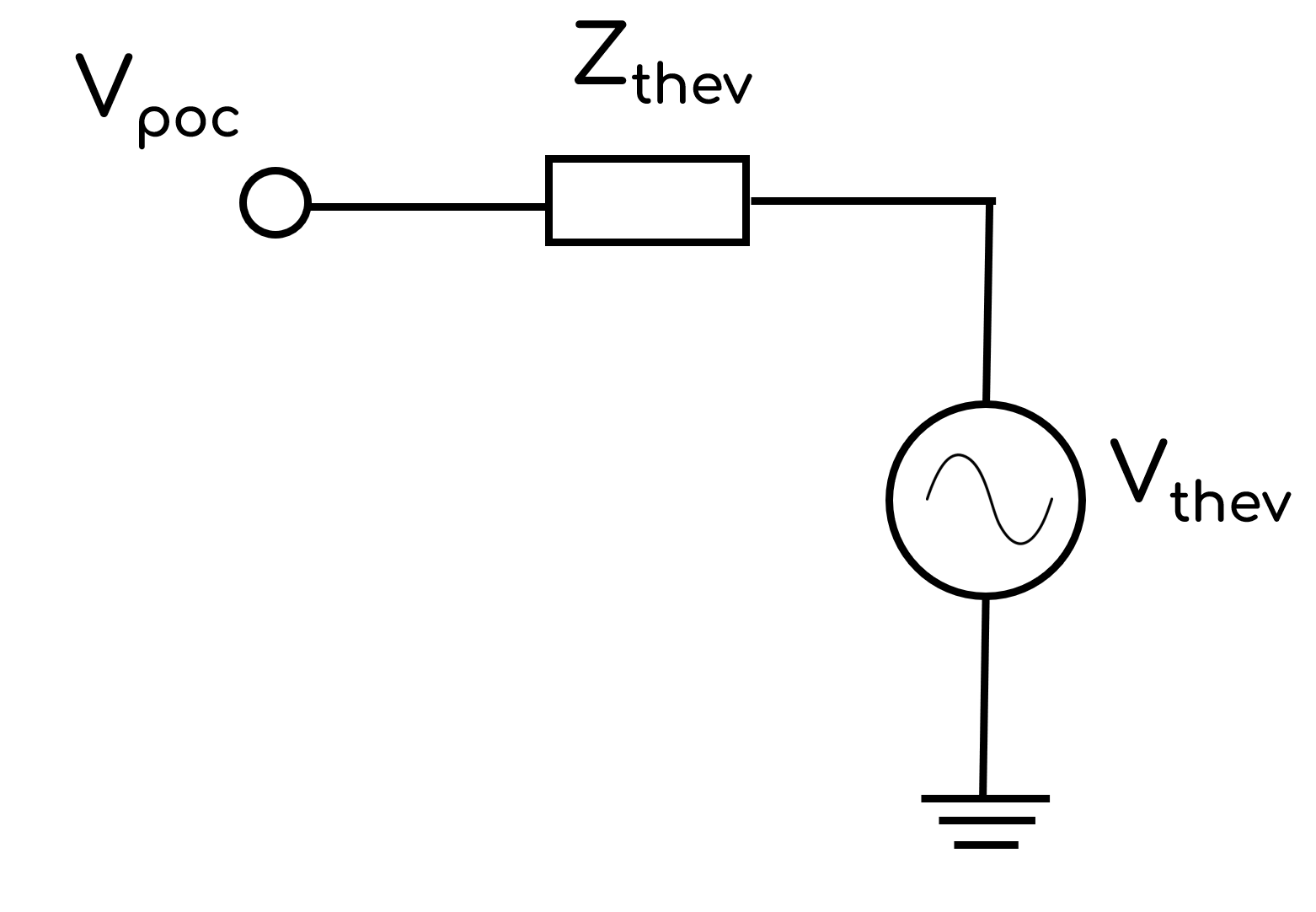
The VDISTURBANCE Command introduces a fault impedance, Zf, in order to achieve a desired voltage disturbance as specified by VCHANGEPU or VPU. There are two calculation methodologies used to calculate Zf:
OP=VDIVIDER; andOP=COMPENSATED.
- OP=VDIVIDER
- OP=COMPENSATED
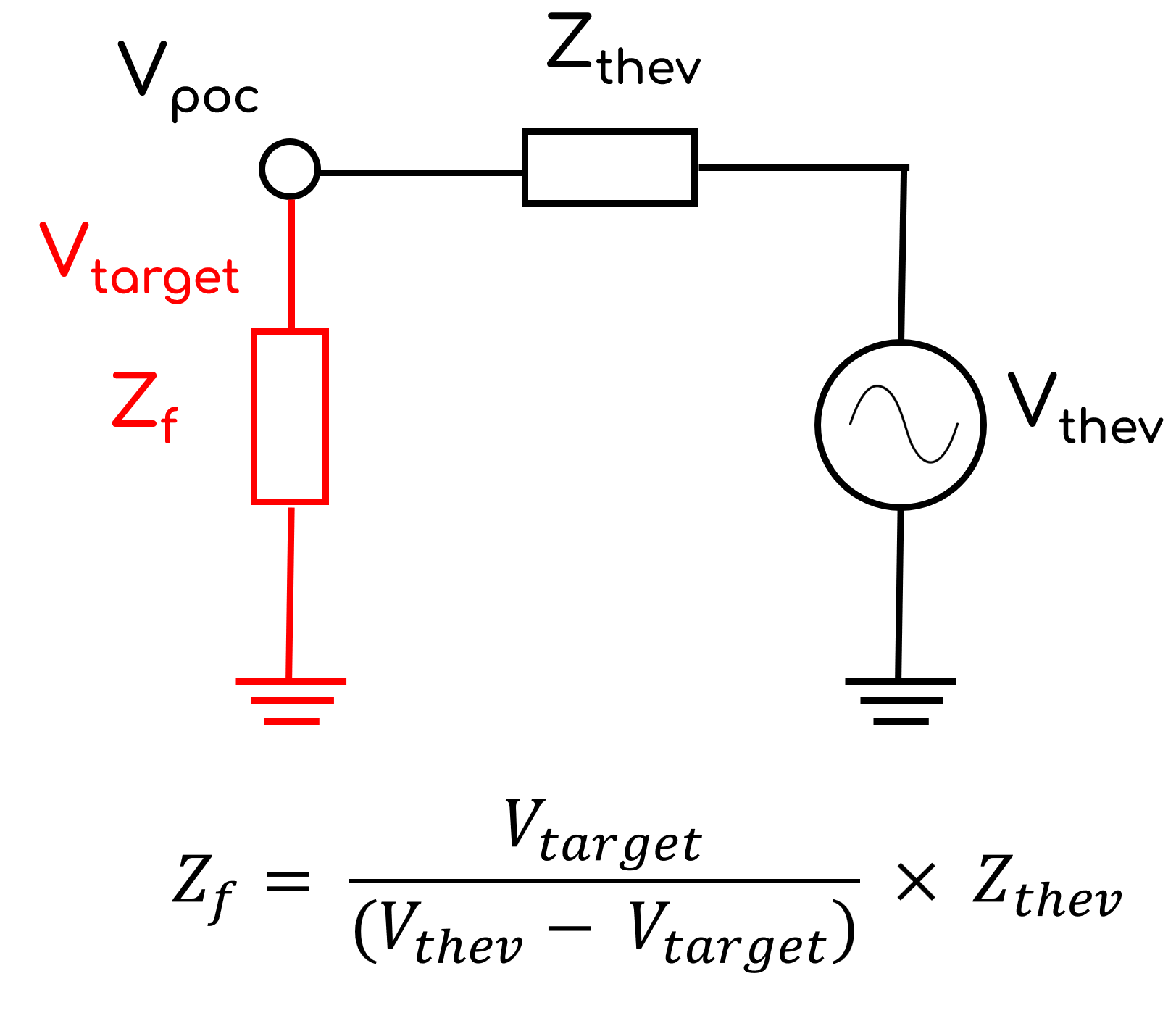
Zf is calculated using voltage divider circuit theory. The formula assumes that the generating system current contribution prior to the disturbance is ≈ 0 (i.e. Vpoc ≈ Vthev) and the generating system current contribution during the disturbance is ≈ 0.
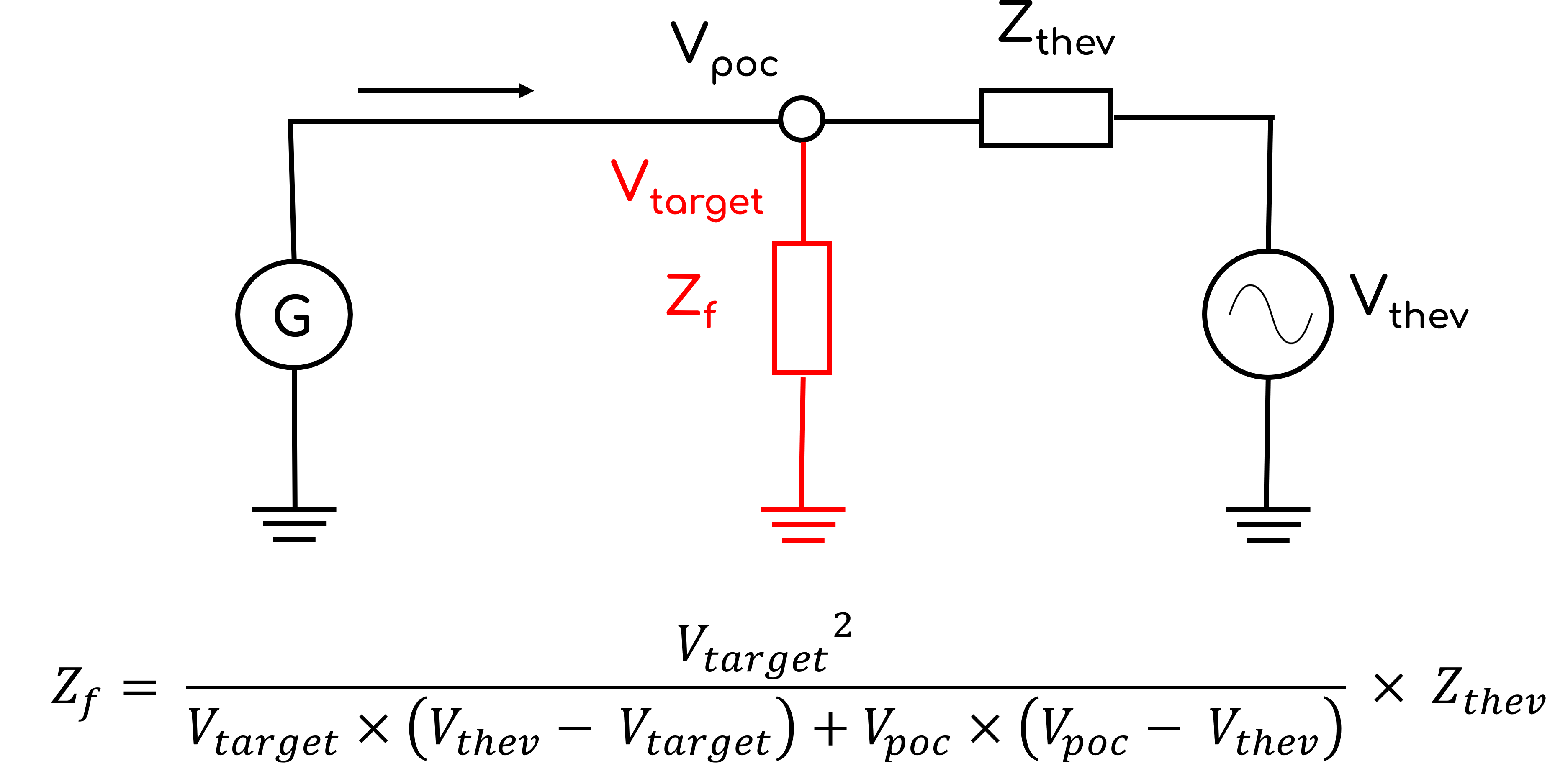
Zf is calculated using an extension of the voltage divider circuit theory which considers generating system contribution prior to voltage disturbances. The formula assumes that the generating system current contribution during the disturbance is the same as prior to the disturbance. This methodology is useful when studying generating systems that have a very low SCR and therefore the assumption of Vpoc ≈ Vthev is no longer valid. Consider the example where a generating system is at PmaxQmax with a low SCR and therefore Vthev = 1.2 [p.u.] to achieve Vpoc = 1.0 [p.u.]. If the user requires a voltage disturbance of 1.2 [p.u.] (i.e. Vtarget = 1.2 [p.u.]), using simple voltage divider circuit theory Zthev would be equal to ∞ and no disturbance would be created!
Example: At 5 seconds, apply a 430 ms voltage disturbance at the connection point which is located at bus 200. The voltage disturbance should cause a -0.1 p.u. relative change in the connection point voltage by applying a 3PH fault. The fault impedance should be calculated using the Thévenin equivalent source impedance (a line called 'Zth' between buses called 'POC' and 'THEV').
VDISTURBANCE, LINE=POC->THEV#Zth, AT=5, DURATION=430, VCHANGEPU=-0.1
At 5 seconds, apply a 500 ms voltage disturbance at the connection point which is located at bus 200. The voltage disturbance should target 1.2 p.u. at the connection point voltage by switching in a capacitor. The fault impedance should be calculated using the Thévenin equivalent source impedance (a line called 'Zth' between buses called 'POC' and 'THEV').
VDISTURBANCE, LINE=POC->THEV#Zth, AT=5, DURATION=500, VPU=1.2
At 5 seconds, apply a 500 ms voltage disturbance at the connection point which is located at bus POC. The voltage disturbance should target 1.2 p.u. at the connection point voltage by switching in a capacitor. The capacitance should be calculated using the Thévenin equivalent source impedance (a line called 'Zth' between buses called 'POC' and 'THEV').
At 10 seconds, once the previous disturbance has cleared, apply another 500 ms voltage disturbance at the connection point which is located at bus POC. The voltage disturbance should target 0.35 p.u. at the connection point voltage by applying a 3PH fault. The fault impedance should be calculated using the Thévenin equivalent source impedance (a line called 'Zth' between buses called 'POC' and 'THEV').
VDISTURBANCE, LINE=POC->THEV#Zth, AT=5, DURATION=500, VPU=1.2
VDISTURBANCE, LINE=POC->THEV#Zth, AT=10, DURATION=500, VPU=0.35
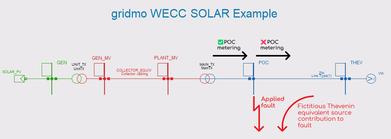
OUTPUT Command
By default when completing SMIB studies, the Thévenin equivalent voltage source and impedance should not be used for POC metering in OUTPUT Commands or in dynamic user models. This is for two reasons:
- SMIB studies: During certain SMIB events (e.g. faults, consideration of distance factor), there will be fictitious Thévenin equivalent source contribution or we will need to break the Thévenin equivalent impedance line into multiple parts to complete the event. See the image below considering the example of applying a fault using
SIMPLEFAULT; and - Network studies: When your generating system is merged into a network model, the Thévenin equivalent voltage source and impedance will no longer be present and therefore can't be referenced.
For clarity:
- ✅ Example of recommended POC metering:
OUTPUT, BUS=POC, VAL=V, NAME=i_poc_vOUTPUT, TX=PLANT_MV->POC#MAIN_TX, METERBUS=POC, VAL=P, NAME=i_ch_poc_pOUTPUT, TX=PLANT_MV->POC#MAIN_TX, METERBUS=POC, VAL=Q, NAME=i_ch_poc_q
- ❌ Example of incorrect POC metering:
OUTPUT, BUS=THEV, VAL=V, NAME=i_poc_vOUTPUT, LINE=POC->THEV#Zth, VAL=P, NAME=i_ch_poc_pOUTPUT, LINE=POC->THEV#Zth, VAL=Q, NAME=i_ch_poc_q
Output bus variable
OUTPUT, BUS=, VAL=, [VALSCALE=, VAL_FUNCTION=, AT=], NAME=, [PLOT_STYLE=SOLID, DISPLAY_ONLY=NO, LEGEND=]
Outputs a variable from a bus.
Arguments:
- OUTPUT
- BUS (
str): Case sensitive bus name. - VAL (
str): Bus value. Options:VAL=V: RMS three-phase voltage [p.u.].VAL=VA: RMS line-ground voltage for phase a [p.u.].VAL=VB: RMS line-ground voltage for phase b [p.u.].VAL=VC: RMS line-ground voltage for phase c [p.u.].VAL=V_POS_SEQ: RMS positive sequence voltage [p.u.].VAL=V_NEG_SEQ: RMS negative sequence voltage [p.u.].VAL=V_ZERO_SEQ: RMS zero sequence voltage [p.u.].VAL=F: Frequency [Hz].VAL=ANGLE: Angle [degrees]. Angle is relative to the generator which was specified as the slack generator prior to the start of the dynamic simulation.
- VALSCALE 🔢 (
float)[Optional]: Multiplicative scaling factor applied to the output value (i.e. scaled_output =VALxVALSCALE). Default value is 1. - VAL_FUNCTION 🔢 (
str)[Optional]: Function applied to the output value(s). For example,VAL_FUNCTION=2*VAL+1. Cannot be used in conjunction withVALSCALE. Click here for more information on VAL_FUNCTION syntax and supported functions. - AT (
float)[Optional]: Time in the simulation [s] to extract a single value—the first sample at or after that time. IfAT=is omitted, the output is a time-series channel of values. Options:AT=x🔢 wherexis afloatAT=SIM_STARTAT=SIM_END
- NAME (
str): Output name. Output names must be unique within a Node. - PLOT_STYLE (
str)[Optional]: How this output channel should be plotted on connected Plot Nodes. Defaults toTYPE=SOLID. Options:TYPE=SOLID: A solid line.TYPE=DASHED: A dashed line.
- DISPLAY_ONLY (
bool)[Optional]: IfYES, calculations (such asSETTLING_TIME) will not be performed using this output channel. Default value isNO. - LEGEND (
str)[Optional]: Subplot legend name. Default value is no legend name.
Example: Output the voltage [p.u] at bus 100, name this output "i_poc_v".
OUTPUT, BUS=100, VAL=V, NAME=i_poc_v
Example: Same bus voltage, but export only the final time-step value as a single Internode Variable.
OUTPUT, BUS=100, VAL=V, NAME=i_poc_v_final, AT=SIM_END
Output line variable
OUTPUT, LINE=, [METERBUS=], VAL=, [PBASE=, QBASE=, SBASE=, VALSCALE=, VAL_FUNCTION=, AT=], NAME=, [PLOT_STYLE=SOLID, DISPLAY_ONLY=NO, LEGEND=]
Outputs a variable from a line. Supports several PowerFactory line-like types: ElmLne, ElmSind, ElmSfilt and ElmZpu.
Arguments:
- OUTPUT
- LINE (
pas): Case sensitive line definition. Lines are defined using the following syntax:from_bus_name->to_bus_name#line_name. Values are given at the 'from-side' of the line. - METERBUS (
str)[Optional]: Case sensitive bus name, which is the metering point for theLINE=line. Default value is the 'from' bus name as per theLINE=argument. - VAL (
str): Line value. Options:VAL=P: Active power [MW].VAL=Q: Reactive power [MVAr].VAL=S: Apparent power [MVA].VAL=PF: Power factor [unitless] (positive power factor corresponds to active power travelling towards thetobus from thefrombus). Click here for details on how gridmo calculates power factor.VAL=I: Current [p.u.] on SBASE, where I [p.u.] = S [MVA] / (V [p.u.] * SBASE [MVA]).VAL=ID: Active current [p.u.] on PBASE; where ID [p.u.] = P [MW] / (V [p.u.] * PBASE [MW]).VAL=IQ: Reactive current [p.u.] on QBASE; where IQ [p.u.] = Q [MVAr] / (V [p.u.] * QBASE [MVAr]).VAL=I_POS_SEQ: Positive sequence current [p.u.] on SBASE; where I_POS_SEQ [p.u.] = I1 [p.u.] / (V [p.u.] * SBASE [MVA]).VAL=I_NEG_SEQ: Negative sequence current [p.u.] on SBASE; where I_NEG_SEQ [p.u.] = I2 [p.u.] / (V [p.u.] * SBASE [MVA]).VAL=I_ZERO_SEQ: Zero sequence current [p.u.] on SBASE; where I_ZERO_SEQ [p.u.] = I0 [p.u.] / (V [p.u.] * SBASE [MVA]).VAL=ID_POS_SEQ: Positive sequence active current [p.u.] on PBASE; where ID_POS_SEQ [p.u.] = ID1 [p.u.] / (V [p.u.] * PBASE [MW]).VAL=ID_NEG_SEQ: Negative sequence active current [p.u.] on PBASE; where ID_NEG_SEQ [p.u.] = ID2 [p.u.] / (V [p.u.] * PBASE [MW]).VAL=IQ_POS_SEQ: Positive sequence reactive current [p.u.] on QBASE; where IQ_POS_SEQ [p.u.] = IQ1 [p.u.] / (V [p.u.] * QBASE [MVAr]).VAL=IQ_NEG_SEQ: Negative sequence reactive current [p.u.] on QBASE; where IQ_NEG_SEQ [p.u.] = IQ2 [p.u.] / (V [p.u.] * QBASE [MVAr]).
- PBASE 🔢 (
float)[Optional]: MW base used for Id calculation [MW]. Only required ifVAL=isID,ID_POS_SEQorID_NEG_SEQ. - QBASE 🔢 (
float)[Optional]: MVAr base used for Iq calculation [MVAr]. Only required ifVAL=isIQ,IQ_POS_SEQorIQ_NEG_SEQ. - SBASE 🔢 (
float)[Optional]: MVA base used for I calculation [MVA]. Only required ifVAL=isI,I_POS_SEQ,I_NEG_SEQorI_ZERO_SEQ. - VALSCALE 🔢 (
float)[Optional]: Multiplicative scaling factor applied to the output value (i.e. scaled_output = VAL x VALSCALE). Default value is 1. - VAL_FUNCTION 🔢 (
str)[Optional]: Function applied to the output value(s). For example,VAL_FUNCTION=2*VAL+1. Cannot be used in conjunction withVALSCALE. Click here for more information on VAL_FUNCTION syntax and supported functions. - AT (
float)[Optional]: Time in the simulation [s] to extract a single value—the first sample at or after that time. IfAT=is omitted, the output is a time-series channel of values. Options:AT=x🔢 wherexis afloatAT=SIM_STARTAT=SIM_END
- NAME (
str): Output name. Output names must be unique within a Node. - PLOT_STYLE (
str)[Optional]: How this output channel should be plotted on connected Plot Nodes. Defaults toTYPE=SOLID. Options:TYPE=SOLID: A solid line.TYPE=DASHED: A dashed line.
- DISPLAY_ONLY (
bool)[Optional]: IfYES, calculations (such asSETTLING_TIME) will not be performed using this output channel. Default value isNO. - LEGEND (
str)[Optional]: Subplot legend name. Default value is no legend name.
Example: Output the active power flowing through the line Zth from bus 100 to bus 200 (measured at the 'from-side' of the line). Name this output "i_poc_p".
OUTPUT, LINE=POC->THEV#Zth, VAL=P, NAME=i_poc_p
Example: Output the active power flowing through the line poc_line from bus Collector33 to bus POC (measured at the 'to-side' of the line) . Name this output "i_poc_p_farend".
OUTPUT, LINE=Collector33->POC#poc_line, METERBUS=POC, VAL=P, NAME=i_poc_p_farend
Output transformer variable
OUTPUT, TX=, [METERBUS=], VAL=, [PBASE=, QBASE=, SBASE=, VALSCALE=, VAL_FUNCTION=, AT=], NAME=, [PLOT_STYLE=SOLID, DISPLAY_ONLY=NO, LEGEND=]
Outputs a variable from a transformer.
Arguments:
- OUTPUT
- TX (
pas): Transformer definition. Transformers are defined using the following syntax:bus1_name->bus2_name#tx_name(two-winding transformer) orbus1_name->bus2_name->bus3_name#tx_name(three-winding transformer). - METERBUS (
str)[Optional]: Case sensitive bus name, which is the metering point for theTX=transformer. Default value is the 'from' bus name as per theTX=argument. - VAL (
str): Transformer value. Options:VAL=P: Active power [MW].VAL=Q: Reactive power [MVAr].VAL=S: Apparent power [MVA].VAL=PF: Power factor [unitless] (positive power factor corresponds to active power travelling towards thetobus from thefrombus). Click here for details on how gridmo calculates power factor.VAL=I: Current [p.u.] on SBASE, where I [p.u.] = S [MVA] / (V [p.u.] * SBASE [MVA]).VAL=ID: Active current [p.u.] on PBASE; where ID [p.u.] = P [MW] / (V [p.u.] * PBASE [MW]).VAL=IQ: Reactive current [p.u.] on QBASE; where IQ [p.u.] = Q [MVAr] / (V [p.u.] * QBASE [MVAr]).VAL=I_POS_SEQ: Positive sequence current [p.u.] on SBASE; where I_POS_SEQ [p.u.] = I1 [p.u.] / (V [p.u.] * SBASE [MVA]).VAL=I_NEG_SEQ: Negative sequence current [p.u.] on SBASE; where I_NEG_SEQ [p.u.] = I2 [p.u.] / (V [p.u.] * SBASE [MVA]).VAL=I_ZERO_SEQ: Zero sequence current [p.u.] on SBASE; where I_ZERO_SEQ [p.u.] = I0 [p.u.] / (V [p.u.] * SBASE [MVA]).VAL=ID_POS_SEQ: Positive sequence active current [p.u.] on PBASE; where ID_POS_SEQ [p.u.] = ID1 [p.u.] / (V [p.u.] * PBASE [MW]).VAL=ID_NEG_SEQ: Negative sequence active current [p.u.] on PBASE; where ID_NEG_SEQ [p.u.] = ID2 [p.u.] / (V [p.u.] * PBASE [MW]).VAL=IQ_POS_SEQ: Positive sequence reactive current [p.u.] on QBASE; where IQ_POS_SEQ [p.u.] = IQ1 [p.u.] / (V [p.u.] * QBASE [MVAr]).VAL=IQ_NEG_SEQ: Negative sequence reactive current [p.u.] on QBASE; where IQ_NEG_SEQ [p.u.] = IQ2 [p.u.] / (V [p.u.] * QBASE [MVAr]).
- PBASE 🔢 (
float)[Optional]: MW base used for Id calculation [MW]. Only required ifVAL=isID,ID_POS_SEQorID_NEG_SEQ. - QBASE 🔢 (
float)[Optional]: MVAr base used for Iq calculation [MVAr]. Only required ifVAL=isIQ,IQ_POS_SEQorIQ_NEG_SEQ. - SBASE 🔢 (
float)[Optional]: MVA base used for I calculation [MVA]. Only required ifVAL=isI,I_POS_SEQ,I_NEG_SEQorI_ZERO_SEQ. - VALSCALE 🔢 (
float)[Optional]: Multiplicative scaling factor applied to the output value (i.e. scaled_output = VAL x VALSCALE). Default value is 1. - VAL_FUNCTION 🔢 (
str)[Optional]: Function applied to the output value(s). For example,VAL_FUNCTION=2*VAL+1. Cannot be used in conjunction withVALSCALE. Click here for more information on VAL_FUNCTION syntax and supported functions. - AT (
float)[Optional]: Time in the simulation [s] to extract a single value—the first sample at or after that time. IfAT=is omitted, the output is a time-series channel of values. Options:AT=x🔢 wherexis afloatAT=SIM_STARTAT=SIM_END
- NAME (
str): Output name. Output names must be unique within a Node. - PLOT_STYLE (
str)[Optional]: How this output channel should be plotted on connected Plot Nodes. Defaults toTYPE=SOLID. Options:TYPE=SOLID: A solid line.TYPE=DASHED: A dashed line.
- DISPLAY_ONLY (
bool)[Optional]: IfYES, calculations (such asSETTLING_TIME) will not be performed using this output channel. Default value isNO. - LEGEND (
str)[Optional]: Subplot legend name. Default value is no legend name.
The OUTPUT, TX= Command currently only supports two-winding transformers. If you need to monitor a three-winding transformer, please consider instead using a 'dummy' line and monitoring that line.
Example: Output the apparent power flowing through the transformer called Main TX between bus Collector1 to bus Collector33. Name this output, i_tx_s.
OUTPUT, TX=Collector1->Collector33#Main TX, VAL=S, NAME=i_tx_s
Output generator variable
OUTPUT, GEN=, VAL=, [PBASE=, QBASE=, SBASE=, VALSCALE=, VAL_FUNCTION=, AT=], NAME=, [PLOT_STYLE=SOLID, DISPLAY_ONLY=NO, LEGEND=]
Outputs a variable from a generator.
Arguments:
- OUTPUT
- GEN (
str): Case sensitive generator definition. Generators are defined by their name only. - VAL (
str): Generator value. Options:VAL=P: Active power [MW].VAL=Q: Reactive power [MVAr].VAL=S: Apparent power [MVA].VAL=PF: Power factor [unitless] (positive power factor corresponds to active power exiting the generator). Click here for details on how gridmo calculates power factor.VAL=ID: Active current [p.u.] on PBASE; where ID [p.u.] = P [MW] / (V [p.u.] * PBASE [MW]).VAL=IQ: Reactive current [p.u.] on QBASE; where IQ [p.u.] = Q [MVAr] / (V [p.u.] * QBASE [MVAr]).VAL=I_POS_SEQ: Positive sequence current [p.u.] on SBASE; where I_POS_SEQ [p.u.] = I1 [p.u.] / (V [p.u.] * SBASE [MVA]).VAL=I_NEG_SEQ: Negative sequence current [p.u.] on SBASE; where I_NEG_SEQ [p.u.] = I2 [p.u.] / (V [p.u.] * SBASE [MVA]).VAL=I_ZERO_SEQ: Zero sequence current [p.u.] on SBASE; where I_ZERO_SEQ [p.u.] = I0 [p.u.] / (V [p.u.] * SBASE [MVA]).VAL=ID_POS_SEQ: Positive sequence active current [p.u.] on PBASE; where ID_POS_SEQ [p.u.] = ID1 [p.u.] / (V [p.u.] * PBASE [MW]).VAL=ID_NEG_SEQ: Negative sequence active current [p.u.] on PBASE; where ID_NEG_SEQ [p.u.] = ID2 [p.u.] / (V [p.u.] * PBASE [MW]).VAL=IQ_POS_SEQ: Positive sequence reactive current [p.u.] on QBASE; where IQ_POS_SEQ [p.u.] = IQ1 [p.u.] / (V [p.u.] * QBASE [MVAr]).VAL=IQ_NEG_SEQ: Negative sequence reactive current [p.u.] on QBASE; where IQ_NEG_SEQ [p.u.] = IQ2 [p.u.] / (V [p.u.] * QBASE [MVAr]).
- PBASE 🔢 (
float)[Optional]: MW base used for Id calculation [MW]. Only required ifVAL=isID,ID_POS_SEQorID_NEG_SEQ. - QBASE 🔢 (
float)[Optional]: MVAr base used for Iq calculation [MVAr]. Only required ifVAL=isIQ,IQ_POS_SEQorIQ_NEG_SEQ. - SBASE 🔢 (
float)[Optional]: MVA base used for I calculation [MVA]. Only required ifVAL=isI,I_POS_SEQ,I_NEG_SEQorI_ZERO_SEQ. - VALSCALE 🔢 (
float)[Optional]: Multiplicative scaling factor applied to the output value (i.e. scaled_output = VAL x VALSCALE). Default value is 1. - VAL_FUNCTION 🔢 (
str)[Optional]: Function applied to the output value(s). For example,VAL_FUNCTION=2*VAL+1. Cannot be used in conjunction withVALSCALE. Click here for more information on VAL_FUNCTION syntax and supported functions. - AT (
float)[Optional]: Time in the simulation [s] to extract a single value—the first sample at or after that time. IfAT=is omitted, the output is a time-series channel of values. Options:AT=x🔢 wherexis afloatAT=SIM_STARTAT=SIM_END
- NAME (
str): Output name. Output names must be unique within a Node. - PLOT_STYLE (
str)[Optional]: How this output channel should be plotted on connected Plot Nodes. Defaults toTYPE=SOLID. Options:TYPE=SOLID: A solid line.TYPE=DASHED: A dashed line.
- DISPLAY_ONLY (
bool)[Optional]: IfYES, calculations (such asSETTLING_TIME) will not be performed using this output channel. Default value isNO. - LEGEND (
str)[Optional]: Subplot legend name. Default value is no legend name.
Example: Output the reactive power being injected by the generator SOLAR_PV. Name this output, i_terminal_q.
OUTPUT, GEN=SOLAR_PV, VAL=Q, NAME=i_terminal_q
Output variable from a PowerFactory object
OUTPUT, OBJECT_NAME/FOREIGN_KEY=, VAL=, [CHANNEL_TYPE=,VALSCALE=, VAL_FUNCTION=, AT=], NAME=, [PLOT_STYLE=SOLID, DISPLAY_ONLY=NO, LEGEND=]
Outputs a variable from a PowerFactory object by specifying the complete PowerFactory variable string representation (such as s:Voltage_Dip).
Any variable which can be selected by PowerFactory's Variable Selection window can be output by gridmo.
Arguments:
- OUTPUT
- OBJECT_NAME or FOREIGN_KEY:
- OBJECT_NAME (
str): Name (loc_namefield) of the PowerFactory object to control. - FOREIGN_KEY (
str): Foreign key (for_namefield) of the PowerFactory object to control.
- OBJECT_NAME (
- VAL (
str): PowerFactory complete string representation of the variable to output (see below info block for guidance). - CHANNEL_TYPE (
str)[Optional]: The type of output channel. Specifying the correct value for the output channel will result in more accurate auto-scaling for connectedPlotNodes. Options:CHANNEL_TYPE=PQS: Active power [MW], reactive power [MVAr] or apparent power [MVA].CHANNEL_TYPE=V: Voltage [p.u.].CHANNEL_TYPE=F: Frequency [Hz].CHANNEL_TYPE=ANGLE: Angle [degrees].CHANNEL_TYPE=I: Current [p.u.], active current [p.u.] or reactive current [p.u.]CHANNEL_TYPE=BINARY: Binary outputs, such as LVRT/HVRT trigger flags.CHANNEL_TYPE=TAPRATIO: Transformer tap ratios [p.u.].CHANNEL_TYPE=PF: Power factor [unitless]. Click here for details on how gridmo calculates power factor.CHANNEL_TYPE=PU: Per unit [p.u.] (e.g. reference signals)
- VALSCALE 🔢 (
float)[Optional]: Multiplicative scaling factor applied to the output value (i.e. scaled_output = VAL x VALSCALE). Default value is 1. - VAL_FUNCTION 🔢 (
str)[Optional]: Function applied to the output value(s). For example,VAL_FUNCTION=2*VAL+1. Cannot be used in conjunction withVALSCALE. Click here for more information on VAL_FUNCTION syntax and supported functions. - AT (
float)[Optional]: Time in the simulation [s] to extract a single value—the first sample at or after that time. IfAT=is omitted, the output is a time-series channel of values. Options:AT=x🔢 wherexis afloatAT=SIM_STARTAT=SIM_END
- NAME (
str): Output name. Output names must be unique within a Node. - PLOT_STYLE (
str)[Optional]: How this output channel should be plotted on connected Plot Nodes. Defaults toTYPE=SOLID. Options:TYPE=SOLID: A solid line.TYPE=DASHED: A dashed line.
- DISPLAY_ONLY (
bool)[Optional]: IfYES, calculations (such asSETTLING_TIME) will not be performed using this output channel. Default value isNO. - LEGEND (
str)[Optional]: Subplot legend name. Default value is no legend name.
To find the string representation, go to the PowerFactory Variable Selection window, select the model using the Object drop down in the center of the screen and then select the variables you want gridmo to display. Then select the Editor on the right hand side of the screen to view the string representation.
For dynamic model parameters, you will often need to calculate the dynamic simulation's initial conditions before the parameters are visible in the Variable Selection window.
gridmo can control objects which match the following PowerFactory class types:
*.Elm**.Rel**.Sta**.SetSelect
Example: Output the signal s:Voltage_Dip from the Model with name REEC_A Electrical Control Model and name this output, i_ch_frt.
OUTPUT, OBJECT_NAME=REEC_A Electrical Control Model, VAL=s:Voltage_Dip, NAME=i_ch_frt
Example: Output the signal s:Voltage_Dip from the Model with foreign key SunnySolar_PPC and name this output, i_ch_frt.
OUTPUT, FOREIGN_KEY=SunnySolar_PPC, VAL=s:Voltage_Dip, NAME=i_ch_frt
OUTPUT_FUNCTION Command
OUTPUT_FUNCTION, FUNCTION=, [CHANNEL_TYPE=, AT=], NAME=, [PLOT_STYLE=SOLID, DISPLAY_ONLY=NO, LEGEND=]
Use OUTPUT_FUNCTION when you want to create an output that combines other previously defined outputs within the same Node.
See Math operations for more information on the supported functions.
Arguments:
- OUTPUT_FUNCTION
- FUNCTION (
str): User-defined function. - CHANNEL_TYPE (
str)[Optional]: The type of output channel. Specifying the correct value for the output channel will result in more accurate auto-scaling for connectedPlotNodes. Options:CHANNEL_TYPE=PQS: Active power [MW], reactive power [MVAr] or apparent power [MVA].CHANNEL_TYPE=V: Voltage [p.u.].CHANNEL_TYPE=F: Frequency [Hz].CHANNEL_TYPE=ANGLE: Angle [degrees].CHANNEL_TYPE=I: Current [p.u.], active current [p.u.] or reactive current [p.u.]CHANNEL_TYPE=BINARY: Binary outputs, such as LVRT/HVRT trigger flags.CHANNEL_TYPE=TAPRATIO: Transformer tap ratios [p.u.].CHANNEL_TYPE=PF: Power factor [unitless]. Click here for details on how gridmo calculates power factor.CHANNEL_TYPE=PU: Per unit [p.u.] (e.g. reference signals)
- AT (
float)[Optional]: Time in the simulation [s] to extract a single value—the first sample at or after that time. IfAT=is omitted, the output is a time-series channel of values. Options:AT=x🔢 wherexis afloatAT=SIM_STARTAT=SIM_END
- NAME (
str): Output name. Output names must be unique within a Node. - PLOT_STYLE (
str)[Optional]: How this output channel should be plotted on connected Plot Nodes. Defaults toTYPE=SOLID. Options:TYPE=SOLID: A solid line.TYPE=DASHED: A dashed line.
- DISPLAY_ONLY (
bool)[Optional]: IfYES, calculations (such asSETTLING_TIME) will not be performed using this output channel. Default value isNO. - LEGEND (
str)[Optional]: Subplot legend name. Default value is no legend name.
Example: Calculate the sum of the active power from two lines and name the output i_p_line_sum.
OUTPUT, LINE=POC->THEV#Zth, VAL=P, NAME=i_p_line1
OUTPUT, LINE=OtherLine->THEV#Zth, VAL=P, NAME=i_p_line2

OUTPUT_FUNCTION, FUNCTION={{i_p_line1}}+{{i_p_line2}}, NAME=i_p_line_sum
Advanced Parameters
The below default values align with the requirements as per Appendix A1 of AEMO's Dynamic Model Acceptance Guidelines (Appendix A1, item 15) released November 2021.
sim.timestep
- Description: Simulation time step.
- Type:
float - Units: [s]
- Default: 0.001
- Range: 0.001 to 0.01
sim.timestep=value