PSCAD™
Introduction
The PSCAD™ Node performs electromagnetic transient type dynamic study simulations which are powered by PSCAD™, a 3rd party power systems software.
This Node is typically used for the following:
- Completing dynamic studies (e.g. validating Generator Performance Standards).
- Benchmarking plant models (e.g. comparing the performance of PSS®E and PSCAD™ plant models).
Check our system requirements page for information on which PSCAD™ versions are currently supported.
smiby
To enable all Commands and features of the PSCAD™ Node, the smiby block needs to be added to the PSCAD™ model and be connected at the plant's connection point. smiby is available for download in our model library.
Bring-your-own external grid representation is possible without using smiby, but would require extensive manual configuration using SET or CONTROL Commands and is therefore not recommended.
Launch modes
Two launch modes are supported:
- Standard mode [Default]: Build and run simulation executables using PSCAD™. Standard mode is recommended for most users as it requires no additional configuration.
- Direct (EMTDC™) mode: Build simulation Fortran executable using PSCAD™ and run simulation executable directly. Direct (EMTDC™) mode is recommended when running a large number of simulations due to speed improvements. The additional configuration requirements of this mode are completed during the Engine setup process, if you select to configure this mode.
User inputs
Select model
Workspace
Defines the input directory and file name of the PSCAD™ Workspace file, including the .pswx file extension.
Example:
sunny-solar-farm\SMIB.pswx
File paths are relative to the Engine's 'inputs' directory, as defined by the Engine configuration parameter dirs.inputs. For example, if dirs.inputs was set as C:\Users\johnsmith\gridmo\Inputs\:
| Absolute file path | Relative file path (required by gridmo) |
|---|---|
| C:\Users\johnsmith\gridmo\Inputs\sunny-solar-farm\SMIB.pswx | sunny-solar-farm\SMIB.pswx |
gridmo requires that all relevant PSCAD™ Case files (.pscx) are located in the same directory or a subdirectory of the PSCAD™ Workspace file (.pswx). This ensures that the Workspace uses relative file path references to the Case files.
Initialize from snapshot
- Initializing from a snapshot is not supported when running a PNI/ENI project.
- Initializing from a snapshot is not supported when running PSCAD™ v5.0.1. This version contains a bug which prevents outfile generation when using snapshots.
- When initializing from a snapshot (from linked node or snapshot file), PSCAD™ will always log the warning "Namespace x has been modified since the snapshot file y was created".
The following options are available:
- None: The PSCAD™ workspace is compiled and run without using a snapshot.
- From linked PSCAD™ Node: The PSCAD™ workspace is initialized from a snapshot file which was created in a linked
PSCAD™Node. - Snapshot file: The PSCAD™ workspace is initialized from a custom snapshot file.
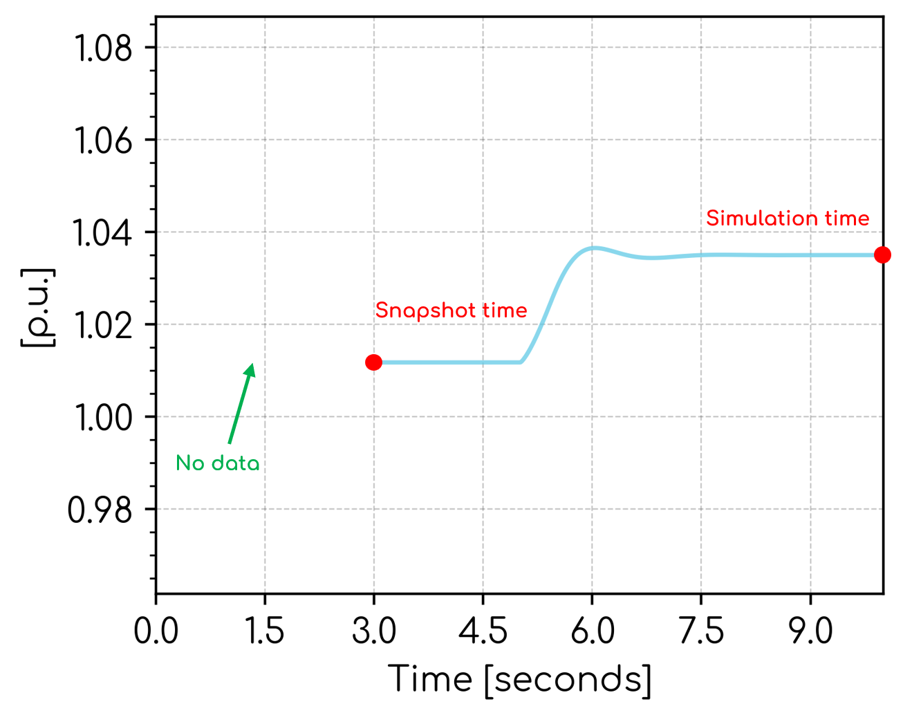
A snapshot file contains a 'snapshot' of a model and its parameters at one particular time step (i.e. the snapshot time). The snapshot file doesn't contain data prior to the snapshot time. Therefore, when a simulation uses a snapshot file, there will be no data shown prior to the snapshot time, as shown in the image below.
It is possible to have the data start from time zero by activating the PSCAD™ case setting, "Remove time offset when starting from snapshot". However, we have chosen not to use this setting for the following reasons:
- Activating the setting would make it visually more difficult for an engineer to appreciate whether a simulation is using snapshots and how long the model takes to initialize.
- EMTDC™ does not use this setting. During the simulation, EMTDC™ applies no time offset, starts running from the snapshot time and all test events must be at times after the snapshot time. Then, only after the simulation is complete, does PSCAD™ apply the time offset. Therefore, you could have situations where users create a snapshot at 3 seconds, only runs the simulation for 1 second but needs to remember to apply test events at times after 3 seconds. This was thought to be very confusing.
If you wish to avoid showing the subplot prior to the snapshot time, we recommend configuring the Plot Node x-axis: Min setting.
The PSCAD™ workspace file, cases, libraries and any external dependencies must be identical between the Node that created the snapshot and the Node which launches with it.
Define simulation
Simulation time
Defines the duration of the dynamic study in seconds.
Example: Run a 30 second dynamic simulation.
30
The minimum simulation time is 0.1 seconds.
🔢 Supports mathematical operations.
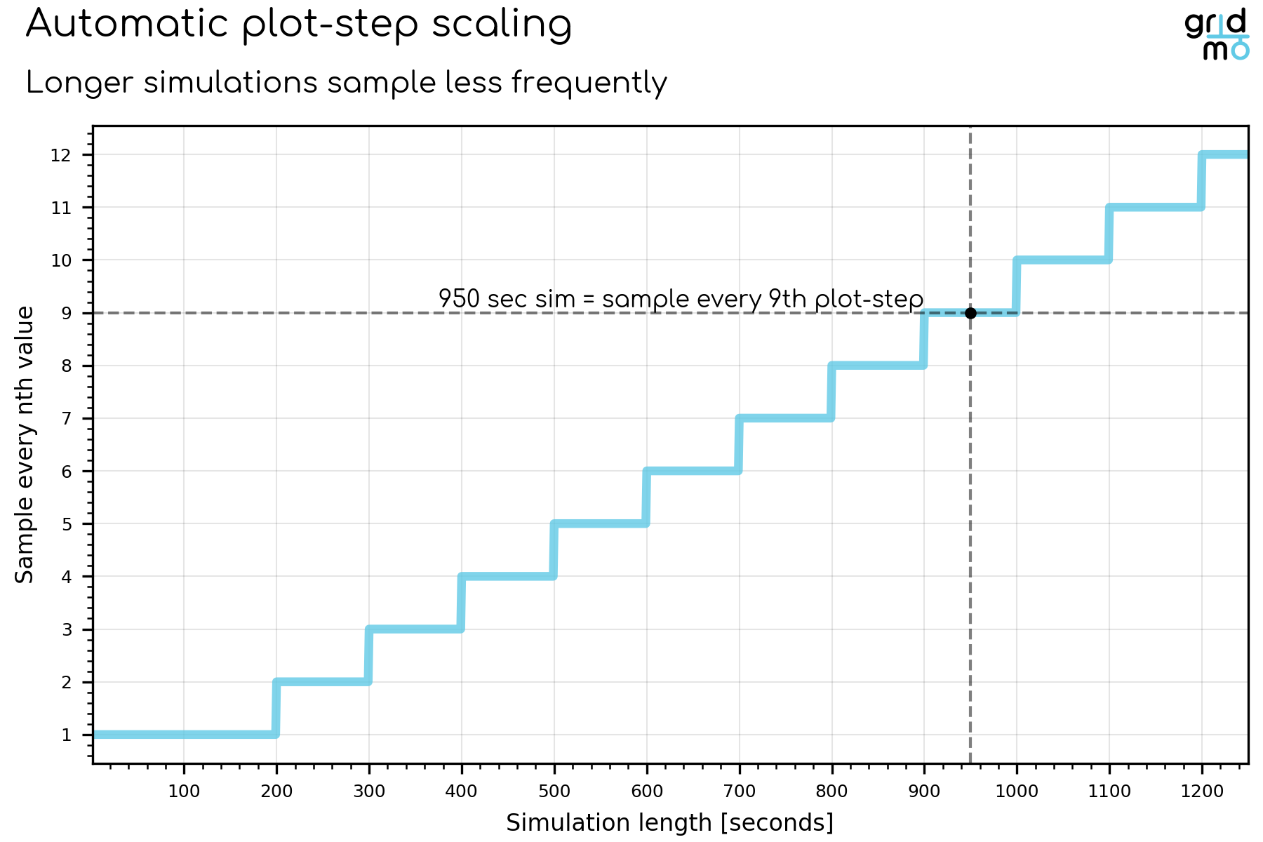
The resolution of the output data (plot step) is automatically reduced if the simulation time is above 200 seconds.
This is to reduce size of output files and temporary files generated during the simulation.
For example, if gridmo is running a 950 second long simulation, the plot step will automatically be increased by a factor of nine based on the below relationship (e.g. if the plot step in your PSCAD™ model is 250 us, then gridmo will automatically change the plot step to 2250 us before launching).
Control Thévenin equivalent source
These controls allow you to define the behavior of the grid.
The grid is modelled as an infinite bus generator for SMIB studies. One of the following may be controlled in a Node:
- Voltage [p.u.]
- Frequency [Hz]
- Angle [degrees]
To use SMIB control functionality, your PSCAD™ Case file must be configured with the smiby block.
Voltage
Defines the infinite bus generator voltage throughout the dynamic simulation via the smiby block. Enter a series of time [s], voltage [p.u.] pairs. The voltage is linearly interpolated between points. There are two methods for specifying the voltage - absolute and relative.
If your PSCAD™ dynamic study uses a linked PSS®E Static Node to set the initial infinite bus voltage, it is often convenient to specify the voltage using the relative method, since it will utilise the infinite bus generator voltage solution from that specific case.
Specifying absolute voltage
Defines the infinite bus generator voltage throughout the dynamic simulation by specifying absolute voltage [p.u.].
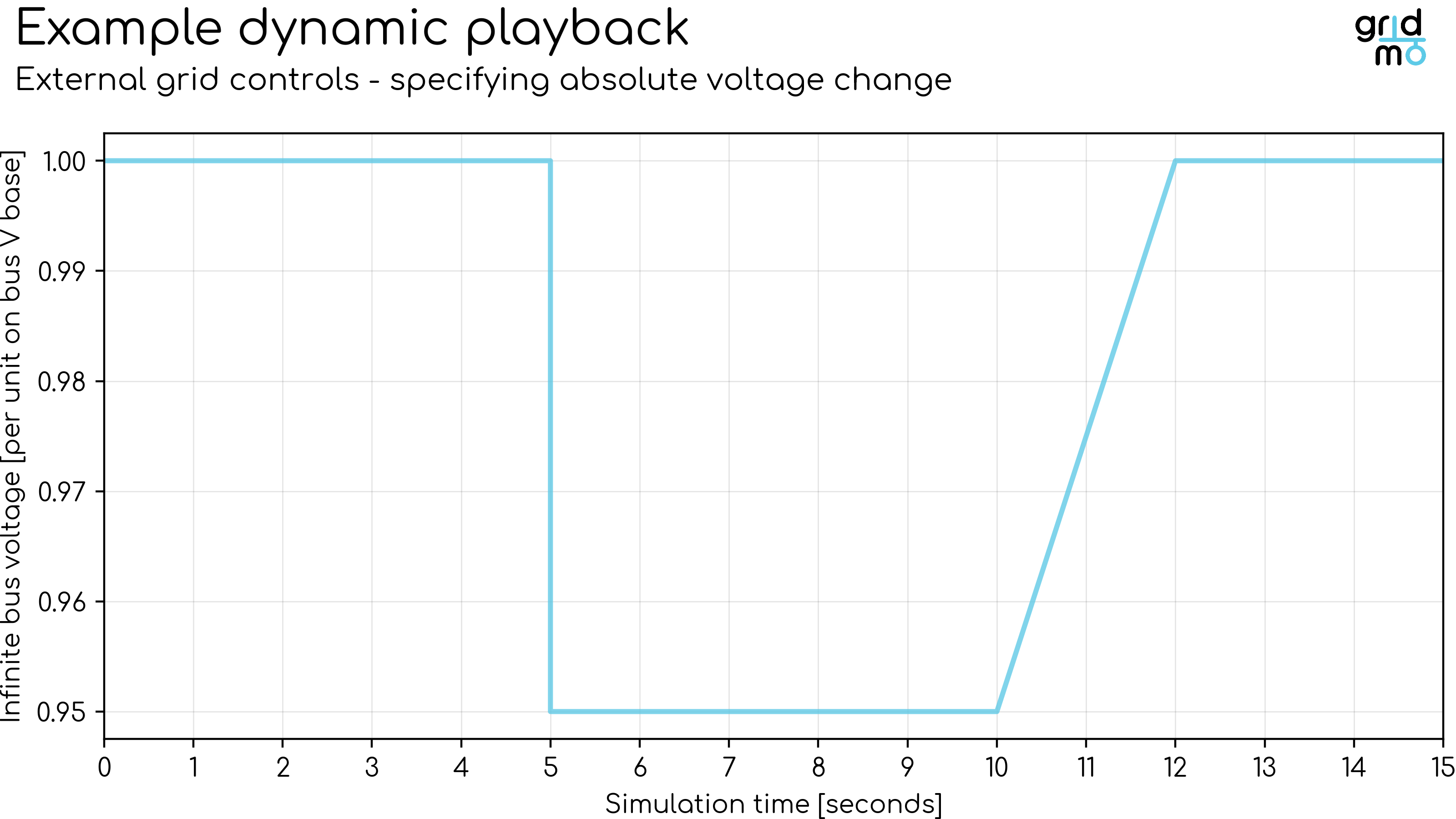
Example: Perform a 15 second dynamic simulation. At 5 seconds, step the voltage from 1.00 [p.u.] to 0.95 [p.u.] in a single rapid step. At 10 seconds, ramp the voltage back up to 1.00 [p.u.] over 2 seconds.
Example
0,      1.00
4.9999, 1.00
5,      0.95
10,     0.95
12,     1.00
15,     1.00
Plot
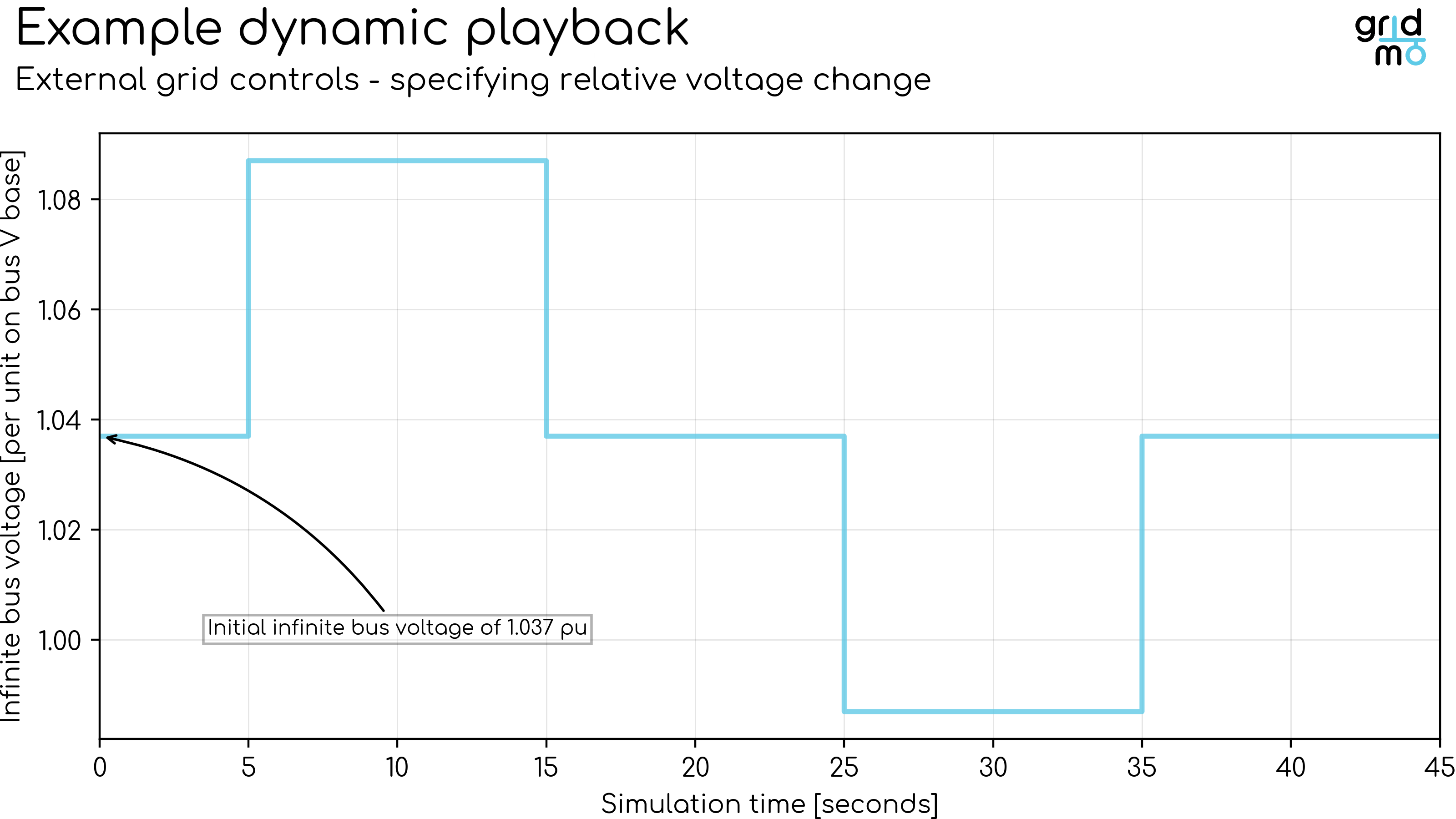
Specifying relative voltage
Defines the infinite bus generator voltage throughout the dynamic simulation by specifying relative voltage [%]. The voltage percentage change is relative to the voltage of the infinite bus generator voltage specified using a SET Command or as specified manually in the smiby block (initial conditions parameter page).
Example: Perform a 45 second dynamic simulation. At 5 seconds, step the voltage up 0.05 per unit (pu) in a single rapid step. At 15 seconds, step the voltage down to its initial value in a single rapid step. At 25 seconds, step the voltage down 0.05 per unit (pu) in a single rapid step. At 35 seconds, step the voltage up to its initial value in a single rapid step.
Example
0,      0 pu
4.999,  0 pu
5,      +0.05 pu
14.999, +0.05 pu
15,     0 pu
24.999, 0 pu
25,     -0.05 pu
34.999, -0.05 pu
35,     0 pu
45,     0 pu
Plot
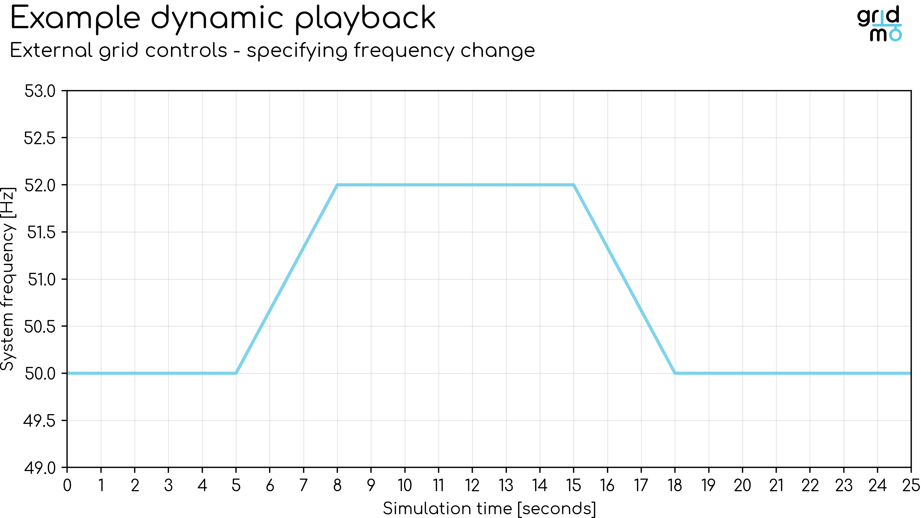
Frequency
Defines the infinite bus frequency throughout the dynamic simulation via the smiby block. Enter a series of time [s], frequency [Hz] pairs. The frequency is linearly interpolated between points.
Example: Perform a 25 second dynamic simulation. At 5 seconds, ramp the frequency up from 50.0 [Hz] to 52.0 [Hz] over 3 seconds. At 15 seconds, ramp the frequency back down to 50.0 [Hz] over 3 seconds.
Example
0,  50
5,  50
8,  52
15, 52
18, 50
25, 50
Plot
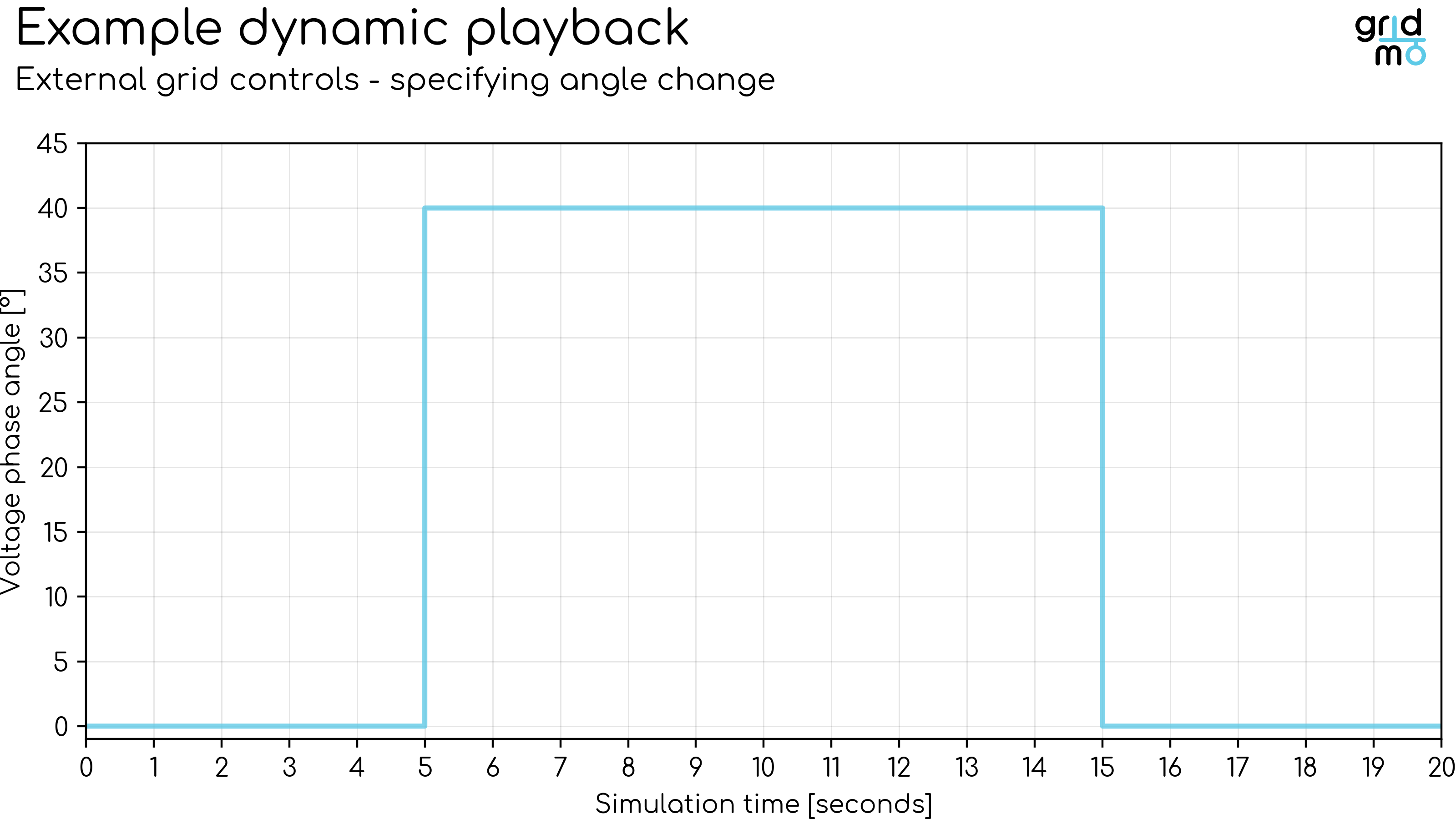
Angle
Defines the infinite bus voltage phase angle throughout the dynamic simulation via the smiby block. Enter a series of time [s], angle [degrees] pairs. The voltage phase angle is not linearly interpolated between points - instead the angle is set to the absolute value at the time specified. The voltage phase angle values specified are relative to the initial angle at the infinite bus - which is typically 0° for SMIB studies.
Voltage phase angle changes are instantaneous. Ramps are not supported.
Example: Perform a 20 second dynamic simulation. At 5 seconds, step the voltage phase angle from 0° to 40°. At 15 seconds, step the voltage phase angle back to 0°.
Example
0,  0
5,  40
15,  0
Plot
Actions
Defines the Commands which configure the dynamic simulation.
Supported Commands:
- Applied BEFORE PSCAD™ is opened:
- SETFILE: Sets the value of a parameter in an external text or configuration file.
- Applied BEFORE simulation has started:
- SET: Sets the status or value of a network element (e.g. bus, line, generator).
- Applied DURING the simulation:
- CONTROL: Controls a network element.
- CONTROL_VDROOPTARGET: Controls a network element using voltage droop control.
- CONTROL_PFTARGET: Controls a network element using power factor control.
- SIMPLEFAULT: Applies a simple power system fault.
- MULTIFAULT: Applies a sequence of power system faults.
- VDISTURBANCE: Applies a relative over or under voltage disturbance using a fault or shunt (capacitor).
- VOLT_OSCIL: Completes a voltage oscillation test.
- FREQ_OSCIL: Completes a frequency oscillation test.
- Old commands (not recommended for new projects):
- Applied DURING the simulation:
- TOVTEST: Completes a Transient Over-Voltage (TOV) test.
- Applied DURING the simulation:
All Action Commands (except SET and SETFILE) include the AT= argument, which specifies the time [s] at which the Command is applied.
SET and SETFILE Commands are applied before the PSCAD™ case is built into the simulation executable. Specifying AT=0 will apply the Command at the very first time step once the dynamic simulation has started.
If you specify the value of the AT= argument beyond the simulation duration (e.g. simulation duration is 20 [s] and AT=25), the Command will not be applied and a warning will be raised.
Define outputs
Outputs
Defines the output channels of the dynamic simulation. The output channels defined here may be used later for plotting and/or further analysis.
Supported Commands:
- OUTPUT: Outputs a network element's dynamic simulation values as an Internode Variable.
By default, each OUTPUT records the full time series for the channel. You can optionally add AT= to store a single Internode Variable sampled from that series—either at a fixed time in seconds, at the start of the simulation using AT=SIM_START or at the end of the simulation using AT=SIM_END—see the OUTPUT Command reference below.
Outputs Description
Defines a short description of the dynamic simulation. This description will appear in the legend of any plot of the data generated by this Node.
Example:
Description here!
Output snapshot
Output snapshots are not supported when running PSCAD™ v5.0.1. This version contains a bug which prevents outfile generation when using snapshots.
If enabled, takes a PSCAD™/EMTDC™ snapshot at the specified time in seconds. No snapshot is taken if this is disabled.
This snapshot can be used in a linked PSCAD™ Node to initialize the PSCAD™ workspace at the snapshot time. See Initialize from snapshot for more details.
Example: Take a snapshot at 4.0 seconds.
4.0
Advanced
PSCAD™ version
Defines the PSCAD™ version used for the Node. Defaults to Engine configuration.
gridmo Engine v1.5.0 onwards supports partial versions. See here for details.
PSCAD™ compiler
Defines the PSCAD™ compiler used for the Node. Defaults to Engine configuration.
Case or Simulation Set
Requires gridmo Engine v1.16.0 or later.
Optional. Selects which PSCAD™ case or simulation set to run within the workspace. The name must match a case or simulation set in the workspace.
When empty, the first case in the workspace is loaded. For workspaces with multiple cases and simulation sets (PNI/ENI projects), all cases in the first simulation set are run instead.
When a case name is specified, only that case is run and the workspace is treated as a non-PNI project.
When a simulation set name is specified, all cases referenced by that simulation set are run.
Example: Run a single case.
comp_testing
Example: Run all cases in a simulation set (PNI/ENI projects).
ENI_test
Distance factor
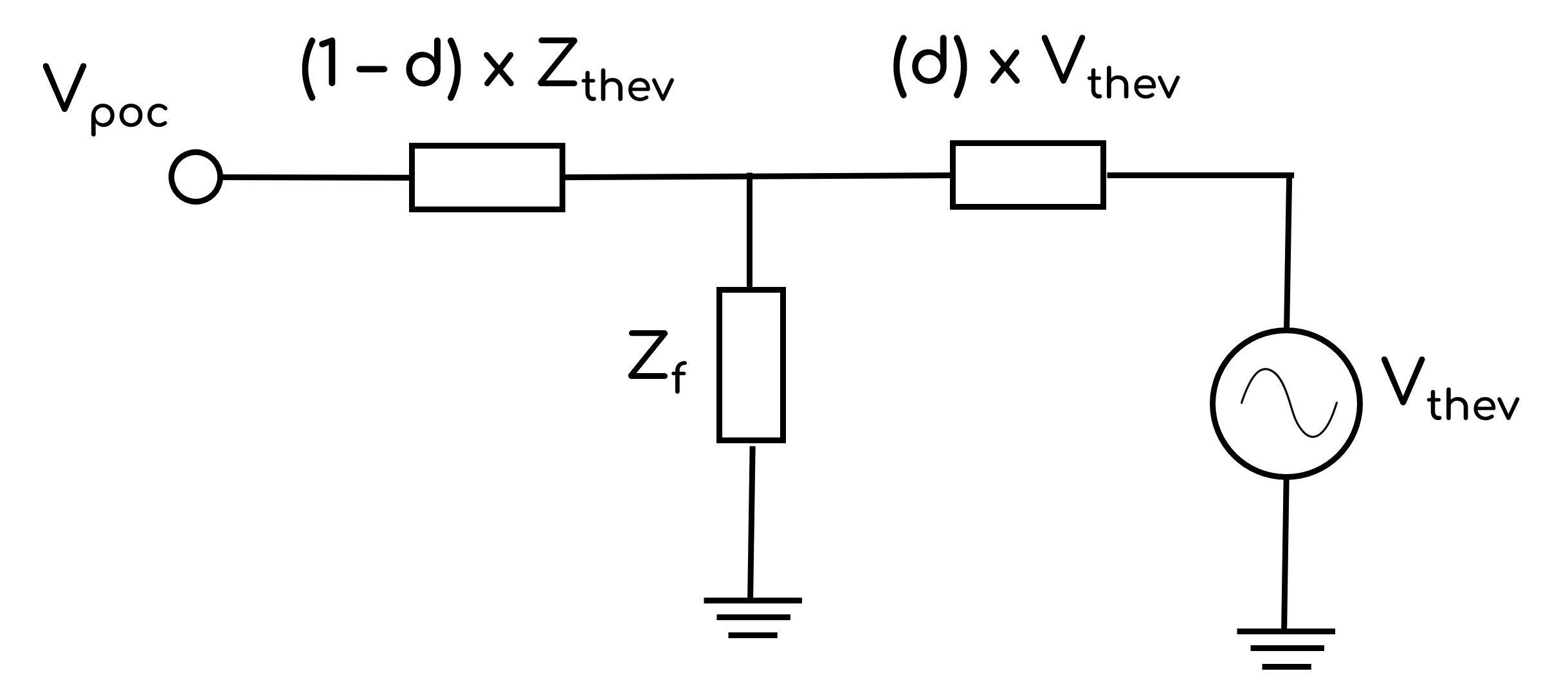
Defines the distance from the connection point at which disturbances are applied. Allowable values are between 0 and 1, where d=1 applies disturbances at the connection point. The image below shows a Thévenin equivalent of the grid as used in SMIB studies, commonly referred to as the 'infinite source', whereby:
- Vthev: Thévenin equivalent voltage source.
- Zthev: Thévenin equivalent impedance.
- Zf: Disturbance impedance.
- d: Distance factor.
- Vpoc: Connection point voltage prior to any disturbance.
Distance factor will apply to all relevant Commands in the Node such as:
TOVTESTVDISTURBANCESIMPLEFAULTMULTIFAULT
Advanced Parameters
Advanced Parameters allow users to configure test details which are not commonly used. Advanced Parameters are often specific to each Node type.
Each line represents a new Advanced Parameter and is entered as a=b format, where a is the name of the Parameter and b is the corresponding value. All Advanced Parameters are set to their default values if they are not included in the Advanced Parameters field.
Example: Set Advanced Parameter, sample.parameter to a value of 5.
sample.parameter=5
API Reference
This section details the Commands and Advanced Parameters specific to the Node.
SETFILE Command
SETFILE, FILENAME=, PARAM/NUMBER=, VAL=
Before PSCAD™ is opened, modifies the FILENAME= external file by finding the PARAM= setting and updating its value to VAL=. Supports basic text formats with delimiters such as comma, space, tab and equals.
Arguments:
- SETFILE
- FILENAME (
str): Defines the relative input directory and file name of the text file to be modified. - PARAM or NUMBER:
- PARAM (
str): Parameter name. If the configuration file has section titles in square brackets, thePARAM=field should be in the format[SectionTitle].ParameterName. - NUMBER (
int): Line number.
- PARAM (
- VAL 🔢 (
floatorintorstr): Value. IfPARAM=is used,VALis the parameter value. IfNUMBER=is used,VALis the value of the entire line in the file.
The text file specified by the FILENAME= field is only modified in the copy of the model in the Engine's working directory. It is not modified in the Engine's inputs folder.
If you need to modify a settings file with format like the below, you can still use the SETFILE command.
You need to set the PARAM= field to [SectionTitle].ParameterName (use the actual values from your settings file) and set the VAL= field to the new value.
[SectionTitle]
ParameterName=0.5
Example: Before PSCAD™ has opened, modify the file windy_wind_farm\ppc_settings.cfg by finding the parameter PPC_Q_ControlMode and set this value to 200.
SETFILE, FILENAME=windy_wind_farm\ppc_settings.cfg, PARAM=PPC_Q_ControlMode, VAL=200
Example: Before PSCAD™ has opened, modify the Ki parameter in the ReactivePower section of the file windy_wind_farm\ppc_settings.ini and set this value to 0.5.
SETFILE, FILENAME=windy_wind_farm\ppc_settings.ini, PARAM=[ReactivePower].Ki, VAL=0.5
SET Command
SET, CNAME/CIID=, PARAM=, [VALSCALE=, VAL_FUNCTION=, STATUS=IN], VAL=
Sets the parameter PARAM= of a PSCAD™ component to the value VAL= before the start of the simulation. Identify the PSCAD™ component by name (CNAME=) or iid (CIID=).
Arguments:
- SET
- CNAME or CIID:
- CNAME (
str): PSCAD™ 'Name' field of the component to set. - CIID (
int): PSCAD™ 'iid' attribute of the component to set.
- CNAME (
- PARAM (
str): Parameter name to set. - VALSCALE 🔢 (
float)[Optional]: Multiplicative scaling factor applied to theVAL(i.e.VALxVALSCALE). Default value is 1. - VAL_FUNCTION 🔢 (
str)[Optional]: Function applied to theVAL. For example,VAL_FUNCTION=2*VAL+1. Cannot be used in conjunction withVALSCALE. Click here for more information on VAL_FUNCTION syntax and supported functions. - STATUS (
str)[Optional]: Sets the enabled/disabled status of the component. Options:IN: Set in-service (equivalent to right clicking on the component and selecting 'Enable' in PSCAD™).OUT: Set out-of-service (equivalent to right clicking on the component and selecting 'Disable' in PSCAD™).
- VAL 🔢 (
floatorintorstr): Value to apply to the parameter.
Setting STATUS=IN on a component will not enable the component if it is on a disabled layer in PSCAD™.
Example: Before the dynamic simulation, set the positive sequence leakage reactance of the two-winding transformer with name MainTX to 0.12 [p.u.].
- Using right-click and
View Propertieson the main transformer block, the positive sequence leakage reactance has parameter nameXl.
SET, CNAME=MainTX, PARAM=Xl, VAL=0.12
Example: Disable the component with the iid 1955742872 before the dynamic simulation.
SET, CIID=1955742872, STATUS=OUT
Example: Before the dynamic simulation, set the LVRT Detection Threshold setting of the unnamed Simple_PPC block to 0.82 [p.u.].
- Using right-click and
View Propertieson the Simple_PPC block, theLVRT Detection Thresholdhas parameter nameLVRT. - Using right-click and
Attributeson the Simple_PPC block, theIdfield reads1955742872.
SET, CIID=1955742872, PARAM=LVRT, VAL=0.82
Example: Enable winding saturation (which is a drop-down combo box) for the transformer with name MainTX.
- Using right-click and
View Propertieson theMainTXtransformer block, theSaturation Enabledfield is aChoicetype parameter. TheChoicetype parameter uses an integer to select the value of the drop-down. Typically, disabled is0and enabled is1- but this is not always the case. - Using right-click and
Edit Parameterson theMainTXtransformer block (combined with theView Propertieswindow) we can see that the parameter with nameEnabis0when saturation is disabled and1when saturation is enabled.
SET, CNAME=MainTX, PARAM=Enab, VAL=1
The smiby block's initial conditions can be set using the same Commands as above. The most common Commands have been added below for convenience:
Set the initial slack bus generator voltage [p.u.] (initial voltage of infinite bus):
SET, CNAME=smiby, PARAM=vinf, VAL=<enter inf bus voltage in per unit>
Set the initial slack bus generator angle [degrees]:
SET, CNAME=smiby, PARAM=ainf, VAL=<enter inf bus angle in degrees>
Set the SCR and X/R of the equivalent network impedance. Note if the CONTROL,CH=SCR, or CONTROL,CH=XR Commands are used, these values are overridden by those Commands.
SET, CNAME=smiby, PARAM=scr_in, VAL=<enter SCR value>
SET, CNAME=smiby, PARAM=xr_in, VAL=<enter X/R value>
CNAME: Finding a component name
The name of a component in PSCAD™ (to use in the CNAME=) field can be found by right-clicking on a component and selecting View Properties. Look for a value in the first column which is equal to Name.
Not all PSCAD™ components have a Name property. Consider using the iid option if there is no name field.
CIID: Finding a component iid
The unique identifier of a PSCAD™ component (the iid, used in the CIID= parameter) can be found by right-clicking on a component and selecting Attributes.
The Id field will have a long series of integers. This value is the IID.
Consider only using the CIID parameter if there is no name parameter for a PSCAD™ component.
If iid needs to be used, consider defining a Global Variable for the iid instead of specifying it in multiple places.
PARAM: Finding a parameter name
The parameter name of a component in PSCAD™ (to use in the PARAM=) field can be found by right-clicking on a component and selecting View Properties.
Click on the Caption field you are interested in controlling. The parameter name can be found in the first column of the highlighted row.
SET_VTHEV Command
SET_VTHEV, VAL_PPOC=, VAL_QPOC=, VAL_VPOC=
Automatically calculates the Thévenin equivalent generator's terminal voltage Vthev given the expected active power, reactive power, and voltage at the point of connection (POC).
Arguments:
- SET_VTHEV
- VAL_PPOC 🔢 (
float): Active power expected at the point of connection (POC) [MW]. - VAL_QPOC 🔢 (
float): Reactive power expected at the point of connection (POC) [MVAr]. - VAL_VPOC 🔢 (
float): Voltage desired at the point of connection (POC) [p.u.].
Example:
- I have added extra Commands to my simulation such that I expect my plant to be injecting 200 MW and 30 MVAr through the connection point into the grid equivalent.
- I have set the system strength (SCR and X/R) I need for this test.
- I want smiby to automatically calculate the Thévenin equivalent generator's terminal voltage
Vthevsuch that I get a point of connection voltage of1.02pu.
SET_VTHEV, VAL_PPOC=200, VAL_QPOC=30, VAL_VPOC=1.02
Equivalent SET Commands
The SET_VTHEV Command is shorthand for the following SET Commands:
SET, CNAME=smiby, PARAM=auto_vinf_enabled, VAL=1
SET, CNAME=smiby, PARAM=auto_vinf_poc_v, VAL=*desired Vpoc*
SET, CNAME=smiby, PARAM=auto_vinf_poc_p, VAL=*expected Ppoc*
SET, CNAME=smiby, PARAM=auto_vinf_poc_q, VAL=*expected Qpoc*
CONTROL Command
CONTROL, CH=, [VALSCALE=, VAL_FUNCTION=, RAMP_FROM_PREVIOUS=NO], AT=, VAL/RELVAL=
Controls the smiby control channel with number CH= to the value of VAL= at AT= seconds after the start of the simulation.
Arguments:
- CONTROL
- CH (
int): Options:CH=1toCH=24: Control asmibychannel (between 1 to 24).CH=SCR: Control the equivalent Thévenin impedance to a value equal to the specified Short Circuit Ratio based on the Project's rated active power [MW] and the line voltage.CH=XR: Control the equivalent Thévenin impedance to a value equal to the specified X/R Ratio.
- VALSCALE 🔢 (
float)[Optional]: Multiplicative scaling factor applied toVALorRELVAL(i.e. new_value =VALxVALSCALEor new_value = old_value + (RELVALxVALSCALE)). Default value is 1. - VAL_FUNCTION 🔢 (
str)[Optional]: Function applied toVALorRELVAL. For example,VAL_FUNCTION=2*VAL+1. Cannot be used in conjunction withVALSCALE. Click here for more information on VAL_FUNCTION syntax and supported functions. - AT 🔢 (
float): Time at which the Command is applied during the dynamic simulation [s]. - VAL or RELVAL:
- VAL 🔢 (
float): New value, expressed absolutely (i.e. new_value =VAL).CH=SCR, VAL=INFcombination controls the equivalent Thévenin impedance to the minimum cross-software stable impedance. AnyXR=Commands are ignored and the X/R ratio is forced to infinity for the entire simulation. - RELVAL 🔢 (
float): New value, expressed relatively (i.e. new_value = old_value +RELVAL).
- VAL 🔢 (
- RAMP_FROM_PREVIOUS (
bool)[Optional]: Defaults toNO. Options:RAMP_FROM_PREVIOUS=YES: The Command will be applied as a linear ramp from the previous Command for that channel. Not supported forCH=SCRorCH=XR.RAMP_FROM_PREVIOUS=NO: The Command will be applied as an immediate change at the time specified with theAT=argument.
If CONTROL, CH=SCR, VAL=INF is present in the dynamic simulation, the X/R ratio of the equivalent Thévenin impedance is forced to infinity. This is to improve benchmarking compared to other software packages. All CONTROL, CH=XR, VAL= arguments are ignored.
CONTROL, CH=SCR, AT=0, VAL= and CONTROL, CH=XR, AT=0, VAL= Commands are typically used in conjunction. These are typically only used in SMIB studies and are used to calculate the Thévenin equivalent source impedance of the Thévenin equivalent generator.
Any VALSCALE/VAL_FUNCTION transformations are applied in addition to any scale factors defined in smiby's output channels.
Only the CH=SCR and CH=XR control channels are linearly interpolated between points. All other smiby control channels (i.e. CH=1 through CH=24) are not linearly interpolated between Commands.
Example:
- Assumes:
smibyis in the PSCAD Workspace and channel #1 has been connected to the generator under test's active power control port.- The
Scale (when enabled)field for channel #1 has been set based on the generator under test's active power control scale (e.g. if per unit control, then scale is1).
- At 5 seconds, set active power to 0.5 [p.u.] of maximum power
- At 15 seconds, set active power to 0.0 [p.u.] of maximum power
- At 25 seconds, set active power to 1.0 [p.u.] of maximum power
CONTROL, CH=1, AT=0, VAL=1
CONTROL, CH=1, AT=5, VAL=0.5
CONTROL, CH=1, AT=15, VAL=0
CONTROL, CH=1, AT=25, VAL=1
Example: Repeat the above example, using relative control steps instead of absolute. This is useful if the initial value is an Internode Variable (as shown below).
CONTROL, CH=1, AT=0, VAL={{i_initial_voltage_setpoint_which_might_not_be_1}}
CONTROL, CH=1, AT=5, RELVAL=-0.5
CONTROL, CH=1, AT=15, RELVAL=-0.5
CONTROL, CH=1, AT=25, RELVAL=+1
Example: Simulate a change in system strength and X/R ratio (simulating a control trip of a remote line) from SCR=10 and XR=4 to SCR=8 and XR=3.6 10 seconds after starting the simulation.
CONTROL, CH=SCR, AT=0, VAL=10
CONTROL, CH=XR, AT=0, VAL=4
CONTROL, CH=SCR, AT=9.9999, VAL=10
CONTROL, CH=XR, AT=9.9999, VAL=4
CONTROL, CH=SCR, AT=10, VAL=8
CONTROL, CH=XR, AT=10, VAL=3.6
Set the system strength of smiby to infinite (as low as possible) for this simulation.
CONTROL, CH=SCR, AT=0, VAL=INF
CONTROL_VDROOPTARGET Command
CONTROL_VDROOPTARGET, QBASE=, DROOP%=, DEADBAND=, QMIN=, QMAX=, AT=, CH=, VAL_VPOC=, VAL_QPOC=, [VALSCALE_QPOC=1, VAL_FUNCTION_QPOC=, VALSCALE=, VAL_FUNCTION=]
Controls the specified smiby control channel by converting a reactive power target into a voltage reference target (which is exported to channel number CH=) based on a droop characteristic.
Arguments:
- CONTROL_VDROOPTARGET
- QBASE 🔢 (
float): Base reactive power [MVAr] for the droop characteristic. - DROOP% 🔢 (
float): Droop percentage [%]. - DEADBAND 🔢 (
float): Voltage deadband [p.u.]. - QMIN 🔢 (
float): Lower reactive power limit of the droop characteristic. - QMAX 🔢 (
float): Upper reactive power limit of the droop characteristic. - AT 🔢 (
float): Time at which the Command is applied during the dynamic simulation [s]. - CH (
int): Options:CH=1toCH=24: Control asmibychannel (between 1 to 24) - typically this will be the voltage reference channel.
- VAL_VPOC 🔢 (
float): Voltage expected at the point of connection [p.u.] based on other commands orsmibydefault control values. - VAL_QPOC 🔢 (
float): Reactive power desired at the point of connection [MVAr, p.u.]. If specified in per unit, useVALSCALE_QPOCto define the base value. - VALSCALE_QPOC 🔢 (
float)[Optional]: Base reactive power [MVAr] for the reactive power desired at the point of connection. Default value is 1. - VAL_FUNCTION_QPOC 🔢 (
str)[Optional]: Function applied to theVAL_QPOC. Defaults toVAL_FUNCTION_QPOC=1*VAL(i.e. no function is applied). Cannot be used in conjunction withVALSCALE_QPOC. Click here for more information on VAL_FUNCTION syntax and supported functions. - VALSCALE 🔢 (
float)[Optional]: Multiplicative scaling factor applied to the value applied to the channel specified with theCH=argument (i.e. channel value =V calculated from droop curvexVALSCALE). Default value is 1. - VAL_FUNCTION 🔢 (
str)[Optional]: Function applied to the value applied to the channel specified with theCH=argument. For example,VAL_FUNCTION=2*VAL+1. Cannot be used in conjunction withVALSCALE. Click here for more information on VAL_FUNCTION syntax and supported functions.
This command is designed to be used for projects which solely use PSCAD™ and do not depend on a static result from PSS®E or PowerFactory.
Example: Set the Vref channel of smiby (which has been configured as channel 4) to the voltage target from a voltage droop curve. The POC voltage is 1.02 per unit and the Q desired at the POC is 25 MVAr. The droop characteristic is 8% droop, on a 35 MVAr base with no deadband and Q limits of +/- 45 MVAr.
CONTROL_VDROOPTARGET, QBASE=35, DROOP%=8, DEADBAND=0, QMIN=-45, QMAX=45, AT=0, CH=4, VAL_VPOC=1.02, VAL_QPOC=25
Example: Set the Vref channel of smiby (which has been configured as channel 4) to the voltage target from a voltage droop curve. The POC voltage is 1.03 per unit and the Q expected at the POC is 0.3 per unit (with a base of 175 MVAr). The droop characteristic is 4% on a 175 MVAr base with no deadband and Q limits of +/- 60 MVAr.
CONTROL_VDROOPTARGET, QBASE=175, DROOP%=4, DEADBAND=0, QMIN=-60, QMAX=60, AT=0, CH=4, VAL_VPOC=1.03, VAL_QPOC=0.3, VAL_FUNCTION_QPOC=175*VAL
CONTROL_PFTARGET Command
CONTROL_PFTARGET, AT=, CH=, VAL_PPOC=, VAL_QPOC=, [VALSCALE_PPOC=1, VAL_FUNCTION_PPOC=, VALSCALE_QPOC=1, VAL_FUNCTION_QPOC=, VALSCALE=, VAL_FUNCTION=]
Controls the specified smiby control channel by converting active and reactive power targets at the POC into a power factor reference (exported to channel CH=).
Arguments:
- CONTROL_PFTARGET
- AT 🔢 (
float): Time at which the Command is applied during the dynamic simulation [s]. - CH (
int): Options:CH=1toCH=24: Control asmibychannel (between 1 to 24) - typically this will be the power factor reference channel.
- VAL_PPOC 🔢 (
float): Active power expected at the point of connection [MW, p.u.] based on other commands orsmibydefault control values. If specified in per unit, useVALSCALE_PPOCto define the base value. - VAL_QPOC 🔢 (
float): Reactive power desired at the point of connection [MVAr, p.u.]. If specified in per unit, useVALSCALE_QPOCto define the base value. - VALSCALE_PPOC 🔢 (
float)[Optional]: Base active power [MW] for the active power expected at the point of connection. Default value is 1. - VAL_FUNCTION_PPOC 🔢 (
str)[Optional]: Function applied to theVAL_PPOC. Defaults toVAL_FUNCTION_PPOC=1*VAL(i.e. no function is applied). Cannot be used in conjunction withVALSCALE_PPOC. Click here for more information on VAL_FUNCTION syntax and supported functions. - VALSCALE_QPOC 🔢 (
float)[Optional]: Base reactive power [MVAr] for the reactive power desired at the point of connection. Default value is 1. - VAL_FUNCTION_QPOC 🔢 (
str)[Optional]: Function applied to theVAL_QPOC. Defaults toVAL_FUNCTION_QPOC=1*VAL(i.e. no function is applied). Cannot be used in conjunction withVALSCALE_QPOC. Click here for more information on VAL_FUNCTION syntax and supported functions. - VALSCALE 🔢 (
float)[Optional]: Multiplicative scaling factor applied to the value applied to the channel specified with theCH=argument (i.e. channel value =Calculated power factor targetxVALSCALE). Default value is 1. - VAL_FUNCTION 🔢 (
str)[Optional]: Function applied to the value applied to the channel specified with theCH=argument. For example,VAL_FUNCTION=2*VAL+1. Cannot be used in conjunction withVALSCALE. Click here for more information on VAL_FUNCTION syntax and supported functions.
A power factor of 0 may result in unexpected behavior for your generating system - as there may not be a way to identify the sign of the reactive power target. We recommend avoiding VAL_PPOC=0 in this command
gridmo has an internal robust power factor definition to avoid ambiguous results, such as P=Q=0. If you have very small VAL_PPOC= or VAL_QPOC= values, the power factor gridmo calculates may be adjusted to avoid these ambiguous results.
Click here for details on how gridmo calculates power factor.
This command is designed to be used for projects which solely use PSCAD™ and do not depend on a static result from PSS®E or PowerFactory.
Example: Set the PFref channel of smiby (which has been configured as channel 3) to the power factor corresponding to active power at the POC of 127 MW and reactive power of 25 MVAr.
CONTROL_PFTARGET, AT=0, CH=3, VAL_PPOC=127, VAL_QPOC=25
Example: Set the PFref channel of smiby (which has been configured as channel 3) to the power factor corresponding to active power at the POC of 1 p.u. and reactive power of 0.3 p.u. The base for both active and reactive power is 175 MW and 175 MVAr respectively.
CONTROL_PFTARGET, AT=0, CH=3, VAL_PPOC=1, VAL_QPOC=0.3, VAL_FUNCTION_PPOC=175*VAL, VAL_FUNCTION_QPOC=175*VAL
CONTROL_CB_POC Command
CONTROL_CB_POC, AT=, STATUS=
Opens or closes the point of connection circuit breaker (POC CB) inside smiby at a specified time.
Arguments:
- CONTROL_CB_POC
- AT 🔢 (
float): Time at which the Command is applied during the dynamic simulation [s]. - STATUS (
str): Options:STATUS=IN: Your plant under test is in-service (circuit breaker is closed).STATUS=OUT: Your plant under test is out of service (circuit breaker is open).
Example: Turn off my generator 20 seconds into the simulation.
CONTROL_CB_POC, AT=20, STATUS=OUT
SIMPLEFAULT Command
SIMPLEFAULT, AT=, DURATION=, [TYPE=3PH, FZ=0, XR=3]
Applies a simple fault within the smiby Thévenin equivalent source impedance.
SIMPLEFAULT is for use in SMIB studies for simpler fault-related performance studies.
More realistic fault scenarios (e.g. including different clearance times and multi-shot auto-reclose), as required in wide area network studies, are not currently supported.
Arguments:
- SIMPLEFAULT
- AT 🔢 (
float): Time at which the fault is applied during the dynamic simulation [s]. - DURATION 🔢 (
float): Fault duration [ms]. When the duration has expired, the fault is removed and the line will remain in service. - TYPE (
str)[Optional]: Fault type. Defaults to3PH. Options:TYPE=3PH: Three phase fault.TYPE=3PHG: Three phase to ground fault.TYPE=2PHG: Two phase to ground fault ('AB' to ground fault).TYPE=PHPH: Phase to phase fault ('A' to 'B' fault).TYPE=PHG: Phase to ground fault ('A' to ground fault).
- FZ [Optional]: Fault impedance. Default value is 0 Ω (i.e. bolted fault). There are two methods for specifying the fault:
- Fault impedance 🔢 (
float): Fault impedance [Ω] (e.g.0.2). - Residual voltage (
str): Residual voltage [%] (e.g. 20%). The percentage is relative to the nominal voltage. This method is used in SMIB studies. Residual voltage is applied by adding series impedance into the fault path. This impedance is calculated assuming a three-phase fault, but only the relevant phase(s) are faulted in the simulation.
- Fault impedance 🔢 (
- XR 🔢 (
float)[Optional]: Reactance to resistance ratio of the fault. Default value is 3.
Using TYPE=PHPH and FZ=X% (residual voltage) will not result in the expected residual voltage during the fault.
The calculated fault impedance does not currently consider the effects of zero sequence impedance.
To benchmark unbalanced faults between PSCAD™ and RMS simulation tools (like PSS®E or PowerFactory), you must plot positive sequence voltage from PSCAD™.
Example:
- Assumes
smibyblock has been configured with the correctSCR,XRand output active and reactive power correctly for the test usingCONTROLCommands. - At 5 seconds, apply a fault at the connection point of the generator under test.
- Fault duration is 430 ms.
- Fault type is two phase to ground.
- Fault impedance is Zf=10 [Ohm].
- X/R ratio of the fault is 3.
Note XR=3, DISTANCE=0% have been omitted, as these are the default values.
SIMPLEFAULT, AT=5, TYPE=2PHG, DURATION=430, FZ=10
Example:
- Assumes
smibyblock has been configured with the correctSCR,XRand output active and reactive power correctly for the test usingCONTROLCommands. - At 5 seconds, apply a fault at the connection point of the generator under test.
- Fault duration is 430 ms.
- Fault type is phase to ground.
- Fault impedance is 0 [ohms].
Note FZ=0, XR=3, DISTANCE=0% have been omitted, as these are the default values.
SIMPLEFAULT, AT=5, TYPE=PHG, DURATION=430
MULTIFAULT Command
MULTIFAULT, AT=, TYPE=, SEQ=, [XR=3, MIN_TIME_BETWEEN_FAULTS=0]
Applies a pre-defined multiple fault sequence in one Command within the smiby Thévenin equivalent source impedance. The first fault is at AT= seconds. Fault X/R ratio and fault distance percentage can also optionally be provided.
MULTIFAULT is typically used in SMIB studies for simple one-Command multiple-fault ride-through (MFRT) studies. For more realistic fault scenarios, as required in wide area network studies, we recommend using the ADVFAULT Command.
Arguments:
- MULTIFAULT
- AT 🔢 (
float): Time at which the first fault in the sequence is applied during the dynamic simulation [s]. - TYPE (
str): Type of multiple fault ride through to apply. Options:TYPE=AEMODMAT: AEMO Dynamic Model Acceptance Tests style MFRT tests.
- SEQ (
str): Type of pre-defined multi fault sequence to apply. Options:- If
TYPE=AEMODMAT:SEQ=Px: Wherexis an integer of 1 to 10.Psequence faults are AEMO DMAT balanced MFRT tests. See below for details.SEQ=Sx: Wherexis an integer of 1 to 10.Ssequence faults are AEMO DMAT unbalanced MFRT tests. See below for details.
- If
- XR 🔢 (
float)[Optional]: Reactance to resistance ratio of the fault. Default value is 3. - MIN_TIME_BETWEEN_FAULTS 🔢 (
float)[Optional]: Minimum time between faults in the sequence [s]. Default value is 0 [s].
- SEQ=P1
- P2
- P3
- P4
- P5
- P6
- P7
- P8
- P9
- P10
MULTIFAULT, AT=5, TYPE=AEMODMAT, SEQ=P1 converts to
SIMPLEFAULT, AT=5.00, TYPE=3PH, DURATION=120, FZ=77.7%
SIMPLEFAULT, AT=7.43, TYPE=3PH, DURATION=120, FZ=66.6%
SIMPLEFAULT, AT=12.65, TYPE=3PH, DURATION=220, FZ=77.7%
SIMPLEFAULT, AT=12.97, TYPE=3PH, DURATION=120, FZ=50%
SIMPLEFAULT, AT=13.59, TYPE=3PH, DURATION=220, FZ=50%
SIMPLEFAULT, AT=15.21, TYPE=3PH, DURATION=120, FZ=50%
SIMPLEFAULT, AT=17.33, TYPE=3PH, DURATION=430, FZ=0%
SIMPLEFAULT, AT=17.95, TYPE=3PH, DURATION=220, FZ=50%
SIMPLEFAULT, AT=18.18, TYPE=3PH, DURATION=220, FZ=16.6%
SIMPLEFAULT, AT=18.41, TYPE=3PH, DURATION=120, FZ=66.6%
SIMPLEFAULT, AT=18.83, TYPE=3PH, DURATION=120, FZ=0%
SIMPLEFAULT, AT=22.05, TYPE=3PH, DURATION=120, FZ=16.6%
SIMPLEFAULT, AT=32.27, TYPE=3PH, DURATION=220, FZ=66.6%
SIMPLEFAULT, AT=33.39, TYPE=3PH, DURATION=120, FZ=50%
SIMPLEFAULT, AT=40.51, TYPE=3PH, DURATION=220, FZ=16.6%
MULTIFAULT, AT=5, TYPE=AEMODMAT, SEQ=P2 converts to
SIMPLEFAULT, AT=5.00, TYPE=3PH, DURATION=220, FZ=50%
SIMPLEFAULT, AT=7.12, TYPE=3PH, DURATION=120, FZ=50%
SIMPLEFAULT, AT=7.84, TYPE=3PH, DURATION=220, FZ=77.7%
SIMPLEFAULT, AT=7.97, TYPE=3PH, DURATION=120, FZ=16.6%
SIMPLEFAULT, AT=13.19, TYPE=3PH, DURATION=120, FZ=66.6%
SIMPLEFAULT, AT=14.41, TYPE=3PH, DURATION=220, FZ=0%
SIMPLEFAULT, AT=14.73, TYPE=3PH, DURATION=120, FZ=50%
SIMPLEFAULT, AT=14.96, TYPE=3PH, DURATION=220, FZ=16.66%
SIMPLEFAULT, AT=25.08, TYPE=3PH, DURATION=430, FZ=50%
SIMPLEFAULT, AT=32.20, TYPE=3PH, DURATION=120, FZ=66.6%
SIMPLEFAULT, AT=33.07, TYPE=3PH, DURATION=120, FZ=0%
SIMPLEFAULT, AT=36.50, TYPE=3PH, DURATION=220, FZ=77.7%
SIMPLEFAULT, AT=38.12, TYPE=3PH, DURATION=120, FZ=77.7%
SIMPLEFAULT, AT=40.24, TYPE=3PH, DURATION=220, FZ=66.66%
SIMPLEFAULT, AT=40.66, TYPE=3PH, DURATION=120, FZ=50%
MULTIFAULT, AT=5, TYPE=AEMODMAT, SEQ=P3 converts to
SIMPLEFAULT, AT=5.00, TYPE=3PH, DURATION=120, FZ=50%
SIMPLEFAULT, AT=5.13, TYPE=3PH, DURATION=120, FZ=50%
SIMPLEFAULT, AT=7.25, TYPE=3PH, DURATION=120, FZ=0%
SIMPLEFAULT, AT=10.37, TYPE=3PH, DURATION=120, FZ=66.6%
SIMPLEFAULT, AT=20.49, TYPE=3PH, DURATION=430, FZ=50%
SIMPLEFAULT, AT=22.92, TYPE=3PH, DURATION=220, FZ=77.7%
SIMPLEFAULT, AT=23.64, TYPE=3PH, DURATION=220, FZ=66.6%
SIMPLEFAULT, AT=25.36, TYPE=3PH, DURATION=120, FZ=16.66%
SIMPLEFAULT, AT=26.48, TYPE=3PH, DURATION=220, FZ=77.7%
SIMPLEFAULT, AT=27.20, TYPE=3PH, DURATION=120, FZ=50%
SIMPLEFAULT, AT=27.52, TYPE=3PH, DURATION=220, FZ=66.6%
SIMPLEFAULT, AT=34.74, TYPE=3PH, DURATION=220, FZ=0%
SIMPLEFAULT, AT=34.97, TYPE=3PH, DURATION=120, FZ=16.66%
SIMPLEFAULT, AT=35.84, TYPE=3PH, DURATION=220, FZ=50%
SIMPLEFAULT, AT=41.06, TYPE=3PH, DURATION=120, FZ=16.66%
MULTIFAULT, AT=5, TYPE=AEMODMAT, SEQ=P4 converts to
SIMPLEFAULT, AT=5.00, TYPE=3PH, DURATION=120, FZ=66.6%
SIMPLEFAULT, AT=7.12, TYPE=3PH, DURATION=120, FZ=50%
SIMPLEFAULT, AT=10.24, TYPE=3PH, DURATION=220, FZ=77.7%
SIMPLEFAULT, AT=10.96, TYPE=3PH, DURATION=220, FZ=0%
SIMPLEFAULT, AT=21.18, TYPE=3PH, DURATION=220, FZ=66.6%
SIMPLEFAULT, AT=28.40, TYPE=3PH, DURATION=220, FZ=50%
SIMPLEFAULT, AT=28.63, TYPE=3PH, DURATION=220, FZ=50%
SIMPLEFAULT, AT=29.85, TYPE=3PH, DURATION=120, FZ=77.7%
SIMPLEFAULT, AT=29.98, TYPE=3PH, DURATION=220, FZ=16.66%
SIMPLEFAULT, AT=30.70, TYPE=3PH, DURATION=120, FZ=16.66%
SIMPLEFAULT, AT=32.32, TYPE=3PH, DURATION=120, FZ=66.6%
SIMPLEFAULT, AT=32.64, TYPE=3PH, DURATION=120, FZ=50%
SIMPLEFAULT, AT=32.96, TYPE=3PH, DURATION=430, FZ=16.66%
SIMPLEFAULT, AT=35.39, TYPE=3PH, DURATION=120, FZ=50%
SIMPLEFAULT, AT=40.51, TYPE=3PH, DURATION=120, FZ=0%
MULTIFAULT, AT=5, TYPE=AEMODMAT, SEQ=P5 converts to
SIMPLEFAULT, AT=5.00, TYPE=3PH, DURATION=220, FZ=77.7%
SIMPLEFAULT, AT=5.23, TYPE=3PH, DURATION=220, FZ=50%
SIMPLEFAULT, AT=5.95, TYPE=3PH, DURATION=120, FZ=50%
SIMPLEFAULT, AT=9.07, TYPE=3PH, DURATION=120, FZ=50%
SIMPLEFAULT, AT=9.20, TYPE=3PH, DURATION=120, FZ=66.6%
SIMPLEFAULT, AT=10.07, TYPE=3PH, DURATION=120, FZ=77.7%
SIMPLEFAULT, AT=17.19, TYPE=3PH, DURATION=220, FZ=0%
SIMPLEFAULT, AT=19.41, TYPE=3PH, DURATION=120, FZ=50%
SIMPLEFAULT, AT=19.73, TYPE=3PH, DURATION=120, FZ=0%
SIMPLEFAULT, AT=29.85, TYPE=3PH, DURATION=120, FZ=66.6%
SIMPLEFAULT, AT=31.97, TYPE=3PH, DURATION=220, FZ=66.6%
SIMPLEFAULT, AT=32.69, TYPE=3PH, DURATION=430, FZ=50%
SIMPLEFAULT, AT=33.32, TYPE=3PH, DURATION=120, FZ=16.66%
SIMPLEFAULT, AT=34.94, TYPE=3PH, DURATION=220, FZ=16.66%
SIMPLEFAULT, AT=40.16, TYPE=3PH, DURATION=220, FZ=16.66%
MULTIFAULT, AT=5, TYPE=AEMODMAT, SEQ=P6 converts to
SIMPLEFAULT, AT=5.00, TYPE=3PH, DURATION=120, FZ=16.66%
SIMPLEFAULT, AT=5.32, TYPE=3PH, DURATION=120, FZ=50%
SIMPLEFAULT, AT=5.45, TYPE=3PH, DURATION=120, FZ=66.6%
SIMPLEFAULT, AT=12.57, TYPE=3PH, DURATION=220, FZ=0%
SIMPLEFAULT, AT=14.79, TYPE=3PH, DURATION=120, FZ=50%
SIMPLEFAULT, AT=14.92, TYPE=3PH, DURATION=120, FZ=50%
SIMPLEFAULT, AT=15.54, TYPE=3PH, DURATION=430, FZ=16.66%
SIMPLEFAULT, AT=25.97, TYPE=3PH, DURATION=220, FZ=16.66%
SIMPLEFAULT, AT=26.94, TYPE=3PH, DURATION=120, FZ=0%
SIMPLEFAULT, AT=30.06, TYPE=3PH, DURATION=220, FZ=66.6%
SIMPLEFAULT, AT=31.28, TYPE=3PH, DURATION=120, FZ=66.6%
SIMPLEFAULT, AT=31.60, TYPE=3PH, DURATION=120, FZ=50%
SIMPLEFAULT, AT=32.22, TYPE=3PH, DURATION=220, FZ=77.7%
SIMPLEFAULT, AT=34.44, TYPE=3PH, DURATION=220, FZ=50%
SIMPLEFAULT, AT=36.16, TYPE=3PH, DURATION=220, FZ=77.7%
MULTIFAULT, AT=5, TYPE=AEMODMAT, SEQ=P7 converts to
SIMPLEFAULT, AT=5.00, TYPE=3PH, DURATION=120, FZ=50%
SIMPLEFAULT, AT=6.62, TYPE=3PH, DURATION=120, FZ=0%
SIMPLEFAULT, AT=6.94, TYPE=3PH, DURATION=120, FZ=50%
SIMPLEFAULT, AT=7.56, TYPE=3PH, DURATION=120, FZ=77.7%
SIMPLEFAULT, AT=8.43, TYPE=3PH, DURATION=120, FZ=66.6%
SIMPLEFAULT, AT=8.75, TYPE=3PH, DURATION=220, FZ=0%
SIMPLEFAULT, AT=8.98, TYPE=3PH, DURATION=220, FZ=66.6%
SIMPLEFAULT, AT=11.20, TYPE=3PH, DURATION=220, FZ=50%
SIMPLEFAULT, AT=14.42, TYPE=3PH, DURATION=430, FZ=50%
SIMPLEFAULT, AT=19.85, TYPE=3PH, DURATION=220, FZ=77.7%
SIMPLEFAULT, AT=21.07, TYPE=3PH, DURATION=120, FZ=16.66%
SIMPLEFAULT, AT=23.19, TYPE=3PH, DURATION=120, FZ=16.66%
SIMPLEFAULT, AT=30.31, TYPE=3PH, DURATION=120, FZ=50%
SIMPLEFAULT, AT=40.43, TYPE=3PH, DURATION=220, FZ=66.6%
SIMPLEFAULT, AT=41.15, TYPE=3PH, DURATION=220, FZ=16.66%
MULTIFAULT, AT=5, TYPE=AEMODMAT, SEQ=P8 converts to
SIMPLEFAULT, AT=5.00, TYPE=3PH, DURATION=120, FZ=16.66%
SIMPLEFAULT, AT=10.12, TYPE=3PH, DURATION=120, FZ=50%
SIMPLEFAULT, AT=10.74, TYPE=3PH, DURATION=430, FZ=66.6%
SIMPLEFAULT, AT=12.17, TYPE=3PH, DURATION=120, FZ=0%
SIMPLEFAULT, AT=15.29, TYPE=3PH, DURATION=220, FZ=0%
SIMPLEFAULT, AT=17.51, TYPE=3PH, DURATION=220, FZ=66.6%
SIMPLEFAULT, AT=17.74, TYPE=3PH, DURATION=220, FZ=50%
SIMPLEFAULT, AT=27.96, TYPE=3PH, DURATION=120, FZ=77.7%
SIMPLEFAULT, AT=28.09, TYPE=3PH, DURATION=220, FZ=16.66%
SIMPLEFAULT, AT=35.31, TYPE=3PH, DURATION=120, FZ=50%
SIMPLEFAULT, AT=35.63, TYPE=3PH, DURATION=220, FZ=66.6%
SIMPLEFAULT, AT=36.05, TYPE=3PH, DURATION=120, FZ=77.7%
SIMPLEFAULT, AT=38.17, TYPE=3PH, DURATION=120, FZ=16.66%
SIMPLEFAULT, AT=39.04, TYPE=3PH, DURATION=120, FZ=50%
SIMPLEFAULT, AT=40.66, TYPE=3PH, DURATION=220, FZ=50%
MULTIFAULT, AT=5, TYPE=AEMODMAT, SEQ=P9 converts to
SIMPLEFAULT, AT=5.00, TYPE=3PH, DURATION=120, FZ=16.66%
SIMPLEFAULT, AT=12.12, TYPE=3PH, DURATION=220, FZ=0%
SIMPLEFAULT, AT=13.09, TYPE=3PH, DURATION=220, FZ=77.7%
SIMPLEFAULT, AT=13.51, TYPE=3PH, DURATION=120, FZ=0%
SIMPLEFAULT, AT=16.63, TYPE=3PH, DURATION=120, FZ=77.7%
SIMPLEFAULT, AT=17.25, TYPE=3PH, DURATION=120, FZ=66.6%
SIMPLEFAULT, AT=19.37, TYPE=3PH, DURATION=220, FZ=50%
SIMPLEFAULT, AT=24.59, TYPE=3PH, DURATION=120, FZ=50%
SIMPLEFAULT, AT=24.72, TYPE=3PH, DURATION=120, FZ=16.66%
SIMPLEFAULT, AT=25.04, TYPE=3PH, DURATION=120, FZ=16.66%
SIMPLEFAULT, AT=26.66, TYPE=3PH, DURATION=430, FZ=66.6%
SIMPLEFAULT, AT=28.09, TYPE=3PH, DURATION=220, FZ=50%
SIMPLEFAULT, AT=30.31, TYPE=3PH, DURATION=220, FZ=50%
SIMPLEFAULT, AT=40.53, TYPE=3PH, DURATION=220, FZ=50%
SIMPLEFAULT, AT=41.25, TYPE=3PH, DURATION=120, FZ=66.6%
MULTIFAULT, AT=5, TYPE=AEMODMAT, SEQ=P10 converts to
SIMPLEFAULT, AT=5.00, TYPE=3PH, DURATION=220, FZ=66.6%
SIMPLEFAULT, AT=5.23, TYPE=3PH, DURATION=120, FZ=16.66%
SIMPLEFAULT, AT=6.35, TYPE=3PH, DURATION=220, FZ=16.66%
SIMPLEFAULT, AT=9.57, TYPE=3PH, DURATION=120, FZ=0%
SIMPLEFAULT, AT=14.69, TYPE=3PH, DURATION=220, FZ=50%
SIMPLEFAULT, AT=21.91, TYPE=3PH, DURATION=120, FZ=50%
SIMPLEFAULT, AT=22.04, TYPE=3PH, DURATION=120, FZ=77.7%
SIMPLEFAULT, AT=22.36, TYPE=3PH, DURATION=220, FZ=50%
SIMPLEFAULT, AT=24.08, TYPE=3PH, DURATION=120, FZ=77.7%
SIMPLEFAULT, AT=24.95, TYPE=3PH, DURATION=120, FZ=66.6%
SIMPLEFAULT, AT=25.57, TYPE=3PH, DURATION=220, FZ=0%
SIMPLEFAULT, AT=35.79, TYPE=3PH, DURATION=430, FZ=66.6%
SIMPLEFAULT, AT=38.22, TYPE=3PH, DURATION=220, FZ=16.66%
SIMPLEFAULT, AT=38.94, TYPE=3PH, DURATION=120, FZ=50%
SIMPLEFAULT, AT=39.26, TYPE=3PH, DURATION=120, FZ=50%
- SEQ=S1
- S2
- S3
- S4
- S5
- S6
- S7
- S8
- S9
- S10
MULTIFAULT, AT=5, TYPE=AEMODMAT, SEQ=S1 converts to
SIMPLEFAULT, AT=10.00, TYPE=3PH, DURATION=100, FZ=20%
SIMPLEFAULT, AT=10.25, TYPE=3PH, DURATION=100, FZ=20%
SIMPLEFAULT, AT=10.50, TYPE=3PH, DURATION=100, FZ=20%
SIMPLEFAULT, AT=13.00, TYPE=2PHG, DURATION=100, FZ=20%
SIMPLEFAULT, AT=16.00, TYPE=2PHG, DURATION=100, FZ=20%
SIMPLEFAULT, AT=18.00, TYPE=2PHG, DURATION=100, FZ=20%
AEMO requires Sequence S1 to contain 6 specific faults and Sequences S2 - S5 to contain 15 randomly generated faults. Refer to the AEMO DMAT requirements for details. For the S1 faults, we have assumed that "Sequence S1 includes application of a 3PHG fault at 5, 5.25, 5.5 seconds..." means that the first fault should be applied 5 seconds after the typical 5 seconds reserved for allowing the model to initialize (i.e. the first fault is applied AT=10).
MULTIFAULT, AT=5, TYPE=AEMODMAT, SEQ=S2 converts to
SIMPLEFAULT, AT=5.00, TYPE=PHG, DURATION=120, FZ=75%
SIMPLEFAULT, AT=7.12, TYPE=2PHG, DURATION=120, FZ=0%
SIMPLEFAULT, AT=8.74, TYPE=2PHG, DURATION=220, FZ=66%
SIMPLEFAULT, AT=9.06, TYPE=3PH, DURATION=220, FZ=66%
SIMPLEFAULT, AT=19.18, TYPE=2PHG, DURATION=220, FZ=0%
SIMPLEFAULT, AT=19.50, TYPE=PHG, DURATION=120, FZ=75%
SIMPLEFAULT, AT=21.72, TYPE=2PHG, DURATION=120, FZ=0%
SIMPLEFAULT, AT=21.95, TYPE=2PHG, DURATION=430, FZ=75%
SIMPLEFAULT, AT=22.57, TYPE=3PH, DURATION=220, FZ=0%
SIMPLEFAULT, AT=29.69, TYPE=PHG, DURATION=120, FZ=75%
SIMPLEFAULT, AT=34.91, TYPE=2PHG, DURATION=120, FZ=75%
SIMPLEFAULT, AT=35.84, TYPE=PHG, DURATION=220, FZ=0%
SIMPLEFAULT, AT=37.06, TYPE=2PHG, DURATION=120, FZ=0%
SIMPLEFAULT, AT=37.93, TYPE=PHG, DURATION=220, FZ=2%
SIMPLEFAULT, AT=38.16, TYPE=PHG, DURATION=120, FZ=66%
MULTIFAULT, AT=5, TYPE=AEMODMAT, SEQ=S3 converts to
SIMPLEFAULT, AT=5.00, TYPE=2PHG, DURATION=120, FZ=66%
SIMPLEFAULT, AT=6.62, TYPE=3PH, DURATION=120, FZ=75%
SIMPLEFAULT, AT=7.24, TYPE=PHG, DURATION=120, FZ=0%
SIMPLEFAULT, AT=7.56, TYPE=2PHG, DURATION=220, FZ=0%
SIMPLEFAULT, AT=8.28, TYPE=2PHG, DURATION=120, FZ=75%
SIMPLEFAULT, AT=13.40, TYPE=PHG, DURATION=430, FZ=0%
SIMPLEFAULT, AT=16.83, TYPE=2PHG, DURATION=120, FZ=75%
SIMPLEFAULT, AT=26.95, TYPE=PHG, DURATION=220, FZ=66%
SIMPLEFAULT, AT=29.17, TYPE=2PHG, DURATION=220, FZ=0%
SIMPLEFAULT, AT=30.14, TYPE=2PHG, DURATION=220, FZ=75%
SIMPLEFAULT, AT=30.56, TYPE=3PH, DURATION=120, FZ=0%
SIMPLEFAULT, AT=32.68, TYPE=2PHG, DURATION=120, FZ=75%
SIMPLEFAULT, AT=32.81, TYPE=PHG, DURATION=220, FZ=66%
SIMPLEFAULT, AT=33.04, TYPE=PHG, DURATION=120, FZ=0%
SIMPLEFAULT, AT=34.16, TYPE=PHG, DURATION=220, FZ=0%
MULTIFAULT, AT=5, TYPE=AEMODMAT, SEQ=S4 converts to
SIMPLEFAULT, AT=5.00, TYPE=PHG, DURATION=220, FZ=66%
SIMPLEFAULT, AT=12.22, TYPE=2PHG, DURATION=120, FZ=66%
SIMPLEFAULT, AT=12.54, TYPE=2PHG, DURATION=120, FZ=0%
SIMPLEFAULT, AT=14.16, TYPE=PHG, DURATION=220, FZ=66%
SIMPLEFAULT, AT=16.38, TYPE=2PHG, DURATION=220, FZ=75%
SIMPLEFAULT, AT=17.35, TYPE=2PHG, DURATION=220, FZ=0%
SIMPLEFAULT, AT=18.07, TYPE=3PH, DURATION=120, FZ=0%
SIMPLEFAULT, AT=23.19, TYPE=2PHG, DURATION=120, FZ=0%
SIMPLEFAULT, AT=23.32, TYPE=2PHG, DURATION=220, FZ=75%
SIMPLEFAULT, AT=24.04, TYPE=PHG, DURATION=220, FZ=75%
SIMPLEFAULT, AT=27.26, TYPE=PHG, DURATION=120, FZ=0%
SIMPLEFAULT, AT=28.38, TYPE=3PH, DURATION=120, FZ=0%
SIMPLEFAULT, AT=28.70, TYPE=2PHG, DURATION=120, FZ=75%
SIMPLEFAULT, AT=28.83, TYPE=PHG, DURATION=430, FZ=75%
SIMPLEFAULT, AT=31.26, TYPE=PHG, DURATION=120, FZ=0%
MULTIFAULT, AT=5, TYPE=AEMODMAT, SEQ=S5 converts to
SIMPLEFAULT, AT=5.00, TYPE=2PHG, DURATION=220, FZ=0%
SIMPLEFAULT, AT=12.22, TYPE=3PH, DURATION=120, FZ=75%
SIMPLEFAULT, AT=12.35, TYPE=2PHG, DURATION=220, FZ=0%
SIMPLEFAULT, AT=12.58, TYPE=2PHG, DURATION=120, FZ=0%
SIMPLEFAULT, AT=22.70, TYPE=2PHG, DURATION=120, FZ=0%
SIMPLEFAULT, AT=23.57, TYPE=PHG, DURATION=120, FZ=75%
SIMPLEFAULT, AT=23.89, TYPE=PHG, DURATION=120, FZ=66%
SIMPLEFAULT, AT=26.01, TYPE=3PH, DURATION=120, FZ=0%
SIMPLEFAULT, AT=29.13, TYPE=2PHG, DURATION=120, FZ=66%
SIMPLEFAULT, AT=30.75, TYPE=PHG, DURATION=220, FZ=0%
SIMPLEFAULT, AT=35.97, TYPE=PHG, DURATION=220, FZ=0%
SIMPLEFAULT, AT=37.19, TYPE=2PHG, DURATION=430, FZ=75%
SIMPLEFAULT, AT=38.12, TYPE=2PHG, DURATION=220, FZ=75%
SIMPLEFAULT, AT=38.54, TYPE=PHG, DURATION=220, FZ=66%
SIMPLEFAULT, AT=40.76, TYPE=PHG, DURATION=120, FZ=75%
MULTIFAULT, AT=5, TYPE=AEMODMAT, SEQ=S6 converts to
SIMPLEFAULT, AT=5.00, TYPE=2PHG, DURATION=220, FZ=75%
SIMPLEFAULT, AT=7.22, TYPE=PHG, DURATION=120, FZ=0%
SIMPLEFAULT, AT=7.35, TYPE=PHG, DURATION=220, FZ=75%
SIMPLEFAULT, AT=17.57, TYPE=2PHG, DURATION=220, FZ=66%
SIMPLEFAULT, AT=18.29, TYPE=PHG, DURATION=120, FZ=0%
SIMPLEFAULT, AT=25.41, TYPE=3PH, DURATION=120, FZ=0%
SIMPLEFAULT, AT=27.53, TYPE=2PHG, DURATION=120, FZ=0%
SIMPLEFAULT, AT=28.65, TYPE=3PH, DURATION=120, FZ=66%
SIMPLEFAULT, AT=33.77, TYPE=PHG, DURATION=220, FZ=75%
SIMPLEFAULT, AT=36.99, TYPE=2PHG, DURATION=120, FZ=66%
SIMPLEFAULT, AT=37.86, TYPE=PHG, DURATION=430, FZ=75%
SIMPLEFAULT, AT=38.49, TYPE=2PHG, DURATION=120, FZ=0%
SIMPLEFAULT, AT=38.81, TYPE=2PHG, DURATION=120, FZ=0%
SIMPLEFAULT, AT=39.43, TYPE=PHG, DURATION=220, FZ=0%
SIMPLEFAULT, AT=39.66, TYPE=2PHG, DURATION=220, FZ=75%
MULTIFAULT, AT=5, TYPE=AEMODMAT, SEQ=S7 converts to
SIMPLEFAULT, AT=5.00, TYPE=PHG, DURATION=220, FZ=75%
SIMPLEFAULT, AT=7.22, TYPE=3PH, DURATION=120, FZ=75%
SIMPLEFAULT, AT=7.84, TYPE=2PHG, DURATION=120, FZ=75%
SIMPLEFAULT, AT=8.46, TYPE=2PHG, DURATION=220, FZ=75%
SIMPLEFAULT, AT=9.43, TYPE=PHG, DURATION=120, FZ=0%
SIMPLEFAULT, AT=9.56, TYPE=PHG, DURATION=220, FZ=0%
SIMPLEFAULT, AT=10.78, TYPE=PHG, DURATION=220, FZ=66%
SIMPLEFAULT, AT=12.50, TYPE=2PHG, DURATION=430, FZ=75%
SIMPLEFAULT, AT=12.94, TYPE=2PHG, DURATION=120, FZ=0%
SIMPLEFAULT, AT=13.26, TYPE=2PHG, DURATION=120, FZ=0%
SIMPLEFAULT, AT=13.58, TYPE=3PH, DURATION=220, FZ=66%
SIMPLEFAULT, AT=18.80, TYPE=2PHG, DURATION=120, FZ=66%
SIMPLEFAULT, AT=25.92, TYPE=PHG, DURATION=120, FZ=0%
SIMPLEFAULT, AT=36.04, TYPE=PHG, DURATION=220, FZ=0%
SIMPLEFAULT, AT=39.26, TYPE=2PHG, DURATION=120, FZ=0%
MULTIFAULT, AT=5, TYPE=AEMODMAT, SEQ=S8 converts to
SIMPLEFAULT, AT=5.00, TYPE=2PHG, DURATION=120, FZ=66%
SIMPLEFAULT, AT=5.13, TYPE=2PHG, DURATION=220, FZ=0%
SIMPLEFAULT, AT=6.85, TYPE=2PHG, DURATION=120, FZ=0%
SIMPLEFAULT, AT=8.97, TYPE=2PHG, DURATION=220, FZ=0%
SIMPLEFAULT, AT=9.69, TYPE=2PHG, DURATION=120, FZ=75%
SIMPLEFAULT, AT=12.81, TYPE=PHG, DURATION=120, FZ=0%
SIMPLEFAULT, AT=19.93, TYPE=PHG, DURATION=120, FZ=0%
SIMPLEFAULT, AT=20.80, TYPE=2PHG, DURATION=220, FZ=66%
SIMPLEFAULT, AT=26.02, TYPE=3PH, DURATION=120, FZ=75%
SIMPLEFAULT, AT=26.15, TYPE=PHG, DURATION=220, FZ=0%
SIMPLEFAULT, AT=26.57, TYPE=PHG, DURATION=220, FZ=66%
SIMPLEFAULT, AT=26.99, TYPE=PHG, DURATION=430, FZ=75%
SIMPLEFAULT, AT=37.42, TYPE=3PH, DURATION=120, FZ=75%
SIMPLEFAULT, AT=38.04, TYPE=2PHG, DURATION=120, FZ=0%
SIMPLEFAULT, AT=40.16, TYPE=PHG, DURATION=220, FZ=75%
MULTIFAULT, AT=5, TYPE=AEMODMAT, SEQ=S9 converts to
SIMPLEFAULT, AT=5.00, TYPE=3PH, DURATION=120, FZ=75%
SIMPLEFAULT, AT=15.12, TYPE=3PH, DURATION=120, FZ=0%
SIMPLEFAULT, AT=18.24, TYPE=PHG, DURATION=220, FZ=0%
SIMPLEFAULT, AT=19.21, TYPE=2PHG, DURATION=120, FZ=0%
SIMPLEFAULT, AT=19.53, TYPE=2PHG, DURATION=120, FZ=66%
SIMPLEFAULT, AT=21.65, TYPE=PHG, DURATION=120, FZ=75%
SIMPLEFAULT, AT=22.77, TYPE=2PHG, DURATION=220, FZ=75%
SIMPLEFAULT, AT=23.19, TYPE=PHG, DURATION=220, FZ=75%
SIMPLEFAULT, AT=23.42, TYPE=PHG, DURATION=220, FZ=66%
SIMPLEFAULT, AT=23.65, TYPE=2PHG, DURATION=120, FZ=66%
SIMPLEFAULT, AT=25.77, TYPE=PHG, DURATION=220, FZ=0%
SIMPLEFAULT, AT=27.49, TYPE=PHG, DURATION=120, FZ=0%
SIMPLEFAULT, AT=28.11, TYPE=2PHG, DURATION=220, FZ=0%
SIMPLEFAULT, AT=35.33, TYPE=2PHG, DURATION=120, FZ=75%
SIMPLEFAULT, AT=40.45, TYPE=2PHG, DURATION=430, FZ=0%
MULTIFAULT, AT=5, TYPE=AEMODMAT, SEQ=S10 converts to
SIMPLEFAULT, AT=5.00, TYPE=2PHG, DURATION=120, FZ=0%
SIMPLEFAULT, AT=7.12, TYPE=PHG, DURATION=120, FZ=75%
SIMPLEFAULT, AT=8.74, TYPE=2PHG, DURATION=120, FZ=0%
SIMPLEFAULT, AT=11.86, TYPE=3PH, DURATION=220, FZ=66%
SIMPLEFAULT, AT=12.09, TYPE=PHG, DURATION=120, FZ=0%
SIMPLEFAULT, AT=12.96, TYPE=PHG, DURATION=430, FZ=0%
SIMPLEFAULT, AT=20.39, TYPE=3PH, DURATION=120, FZ=75%
SIMPLEFAULT, AT=21.01, TYPE=2PHG, DURATION=220, FZ=66%
SIMPLEFAULT, AT=21.43, TYPE=2PHG, DURATION=220, FZ=75%
SIMPLEFAULT, AT=21.66, TYPE=2PHG, DURATION=220, FZ=75%
SIMPLEFAULT, AT=26.88, TYPE=PHG, DURATION=220, FZ=75%
SIMPLEFAULT, AT=37.10, TYPE=PHG, DURATION=220, FZ=0%
SIMPLEFAULT, AT=37.82, TYPE=2PHG, DURATION=120, FZ=66%
SIMPLEFAULT, AT=38.94, TYPE=2PHG, DURATION=120, FZ=0%
SIMPLEFAULT, AT=41.06, TYPE=PHG, DURATION=120, FZ=0%
Example:
- Assumes
smibyblock has been configured with the correctSCR,XRand output active and reactive power correctly for the test usingCONTROLCommands. - At 5 seconds, apply an AEMO DMAT
S1fault sequence at the connection point of the generator under test.
MULTIFAULT, AT=5, TYPE=AEMODMAT, SEQ=S1
TOVTEST Command
TOVTEST Command is no longer recommended for new Projects. Instead, use the VDISTURBANCE Command.
TOVTEST, AT=, QCAP=, DURATION=, [TARGET=]
Completes a Transient Over-Voltage (TOV) test within the smiby block whereby a fixed shunt (capacitor) is switched in service on the connection point of QCAP= MVAr, AT= seconds into the dynamic simulation. The capacitor is removed after DURATION= milliseconds.
Arguments:
- TOVTEST
- AT 🔢 (
float): Time at which the Command is applied during the dynamic simulation [s]. - QCAP 🔢 (
float): Options:QCAP=X(whereXis a number): Size of the capacitor to switch in [MVAr].QCAP=CALC: Enables the automatic calculation of the capacitor size to achieve a target overvoltage based on theTARGET=Argument. Any contribution from the generator under test is not included in this calculation.
- DURATION 🔢 (
float): Disturbance duration [ms]. When the duration has expired, the capacitor is removed. - TARGET 🔢 (
float)[Optional]: Voltage target in per unit for this test. Only required ifQCAP=CALC.
Only one TOVTEST Command is supported in a single PSCAD™ Node.
Example:
Assuming smiby is in the PSCAD™ Workspace, at 10 seconds switch in a capacitor of 15 MVAr at the connection point which, based on the SCR and X/R ratio, gives a TOV of 1.15pu. Switch the capacitor out again after 0.9 seconds.
TOVTEST, AT=10, QCAP=15, DURATION=900
Example:
Assuming smiby is in the PSCAD™ Workspace, at 5 seconds switch in a capacitor large enough to achieve a 1.2 pu over-voltage at the smiby connection point, given the SCR and X/R ratio loaded into the smiby block. Switch the capacitor out again after 0.5 seconds.
TOVTEST, AT=5, QCAP=CALC, TARGET=1.2, DURATION=500
VDISTURBANCE Command
VDISTURBANCE, [OP=VDIVIDER/COMPENSATED], AT=, DURATION=, VCHANGEPU/VPU=, [XR=3]
At AT= seconds after the start of the dynamic simulation, applies a voltage disturbance at the smiby connection point. Depending on the values of VCHANGEPU/VPU, OP and the connection point bus voltage prior to the disturbance, the Command automatically switches between:
- Applying a 3PH fault to create an undervoltage disturbance; or
- Inserting a capacitor to create an overvoltage disturbance.
The disturbance is removed after DURATION= milliseconds.
Arguments:
- VDISTURBANCE
- OP (
str)[Optional]: Calculation methodology. Defaults toOP=VDIVIDER. Options:OP=VDIVIDER: Voltage divider calculation methodology.OP=COMPENSATED: Voltage divider calculation methodology extended to consider generating system contribution prior to voltage disturbances.
- AT 🔢 (
float): Time at which the Command is applied during the dynamic simulation [s]. - DURATION 🔢 (
float): Disturbance duration [ms]. When the duration has expired, the disturbance is removed. - VCHANGEPU or VPU:
- VCHANGEPU 🔢 (
float): Relative voltage disturbance [p.u.]. The voltage is relative to the smiby connection point bus voltage prior to the disturbance. - VPU 🔢 (
float): Absolute voltage disturbance [p.u.].
- VCHANGEPU 🔢 (
- XR 🔢 (
float)[Optional]: Reactance to resistance ratio of the 3PH fault impedance used for undervoltages. Default value is 3. When inserting a capacitor for overvoltage disturbances, XR is ignored.
Multiple VDISTURBANCE Commands are supported in a single Node, which may include a mix of under and over voltage disturbances.
If you are benchmarking with PSS®E Dynamic VDISTURBANCE Command, ensure that smiby distance factor is 1.
Calculation methodology
The image below shows a Thévenin equivalent of the grid as used in SMIB studies, commonly referred to as the 'infinite source', whereby:
- Vthev: Thévenin equivalent voltage source.
- Zthev: Thévenin equivalent impedance.
- Vpoc: Connection point voltage prior to any disturbance.
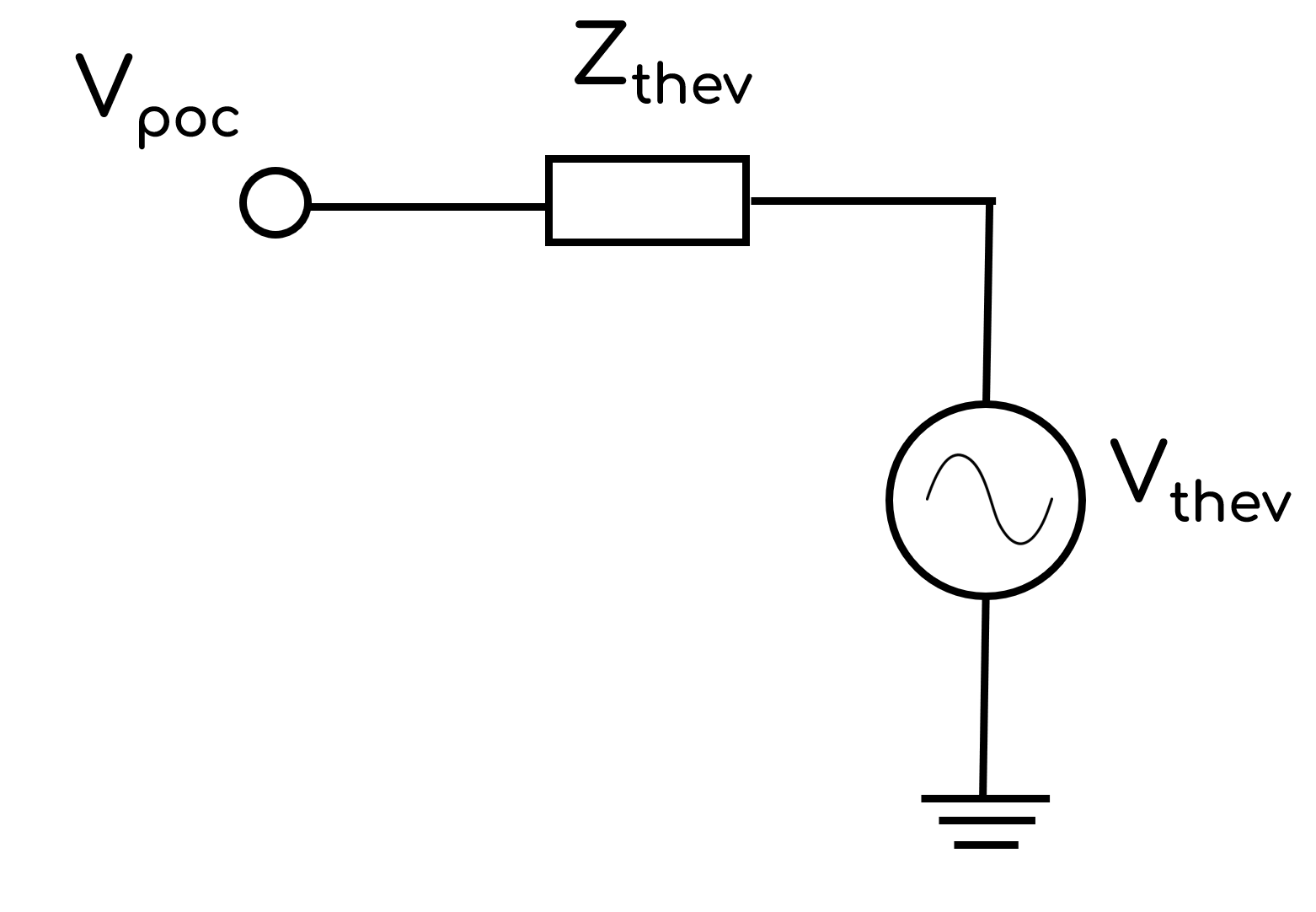
The VDISTURBANCE Command introduces a fault impedance, Zf, in order to achieve a desired voltage disturbance as specified by VCHANGEPU or VPU. There are two calculation methodologies used to calculate Zf:
OP=VDIVIDER; andOP=COMPENSATED.
- OP=VDIVIDER
- OP=COMPENSATED
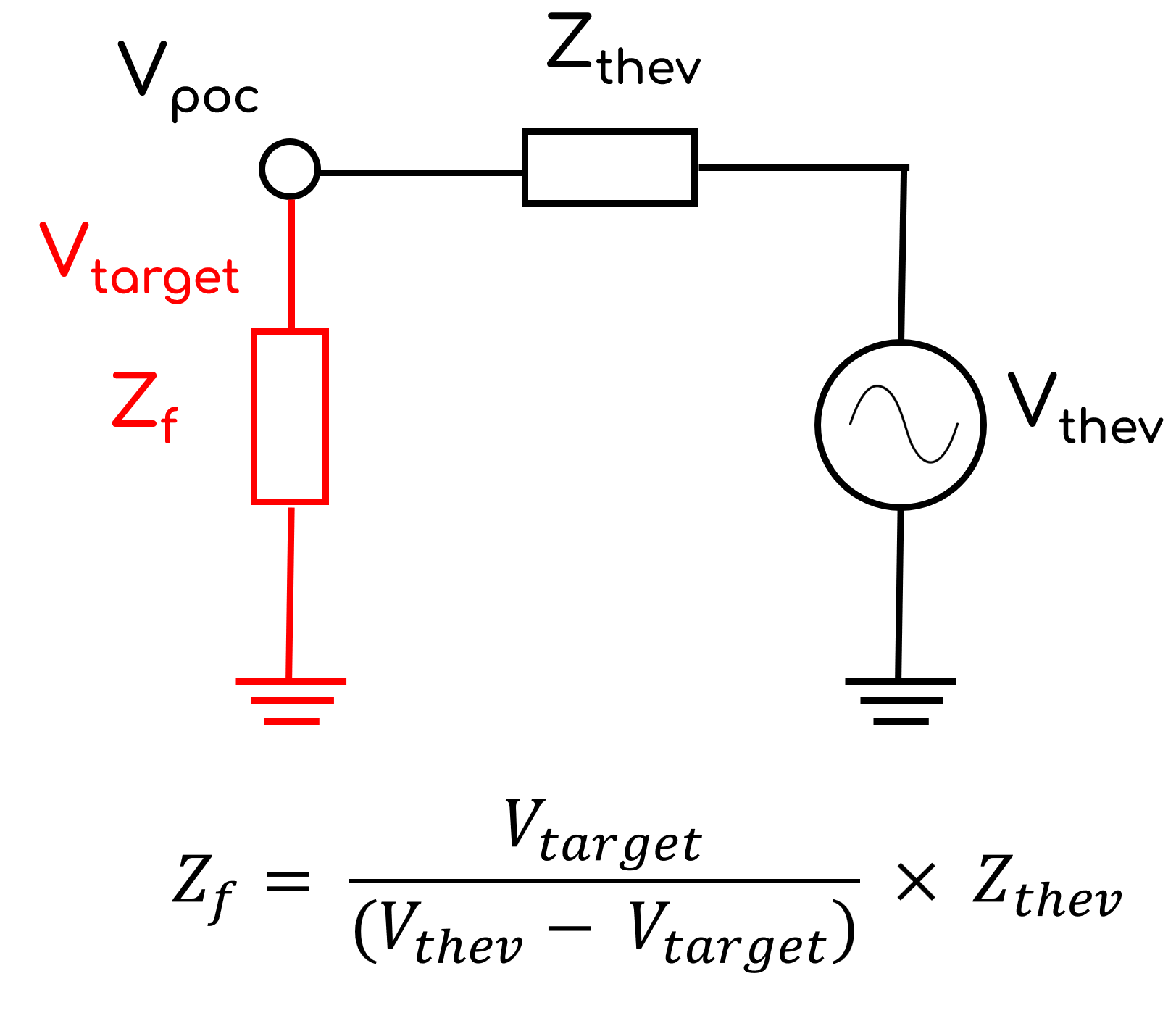
Zf is calculated using voltage divider circuit theory. The formula assumes that the generating system current contribution prior to the disturbance is ≈ 0 (i.e. Vpoc ≈ Vthev) and the generating system current contribution during the disturbance is ≈ 0.
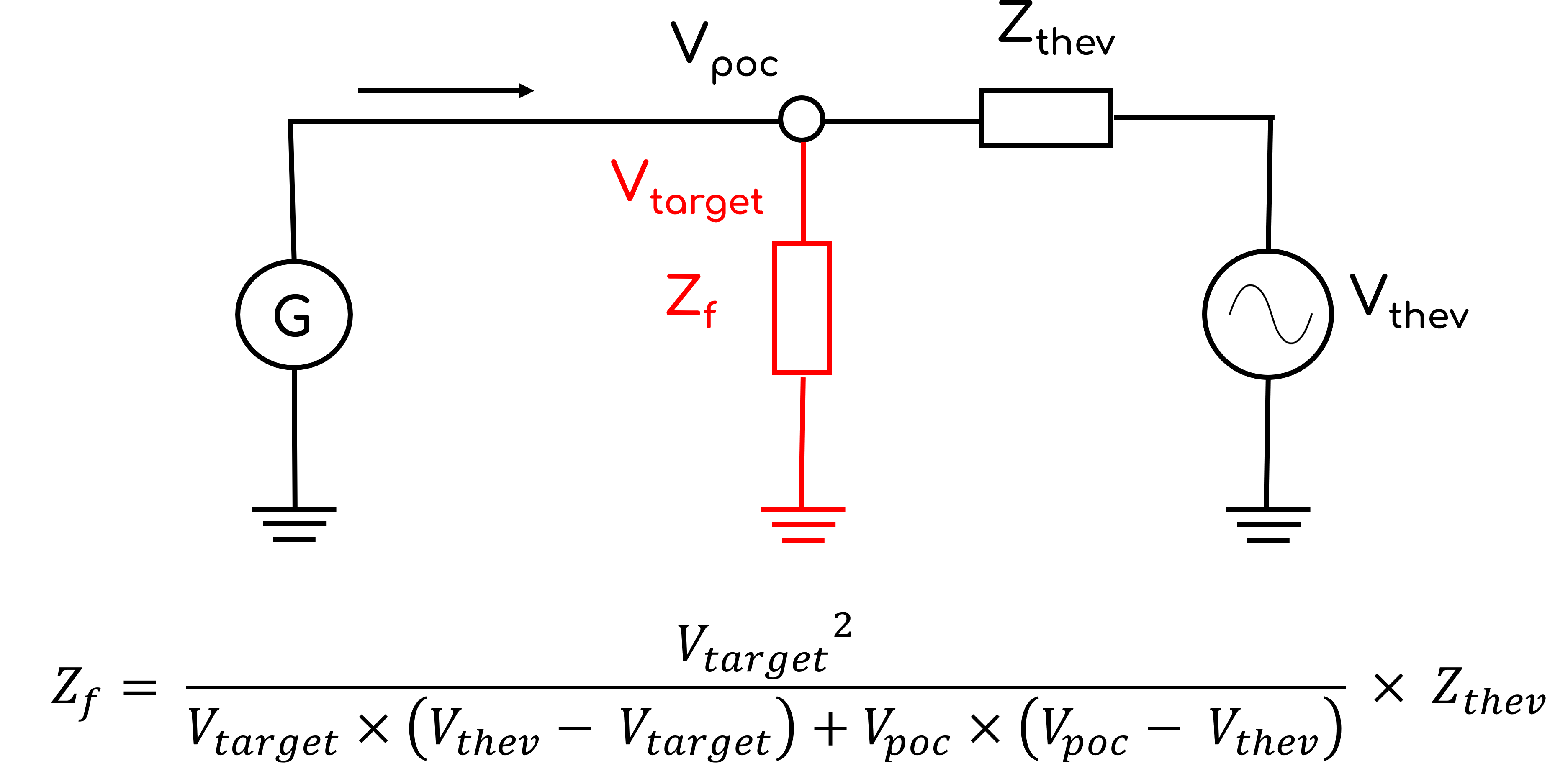
Zf is calculated using an extension of the voltage divider circuit theory which considers generating system contribution prior to voltage disturbances. The formula assumes that the generating system current contribution during the disturbance is the same as prior to the disturbance. This methodology is useful when studying generating systems that have a very low SCR and therefore the assumption of Vpoc ≈ Vthev is no longer valid. Consider the example where a generating system is at PmaxQmax with a low SCR and therefore Vthev = 1.2 [p.u.] to achieve Vpoc = 1.0 [p.u.]. If the user requires a voltage disturbance of 1.2 [p.u.] (i.e. Vtarget = 1.2 [p.u.]), using simple voltage divider circuit theory Zthev would be equal to ∞ and no disturbance would be created!
Example:
Assuming smiby is in the PSCAD™ Workspace, at 5 seconds, apply a 430 ms voltage disturbance at the connection point. The voltage disturbance should cause a -0.1 p.u. relative change in the connection point voltage by applying a 3PH fault.
VDISTURBANCE, AT=5, DURATION=430, VCHANGEPU=-0.1
Assuming smiby is in the PSCAD™ Workspace, at 5 seconds, apply a 500 ms voltage disturbance at the connection point. The voltage disturbance should target 1.2 p.u. at the connection point voltage by switching in a capacitor.
VDISTURBANCE, AT=5, DURATION=500, VPU=1.2
Assuming smiby is in the PSCAD™ Workspace, at 5 seconds, apply a 500 ms voltage disturbance at the connection point. The voltage disturbance should target 1.2 p.u. at the connection point voltage by switching in a capacitor.
Assuming smiby is in the PSCAD™ Workspace, at 10 seconds, once the previous disturbance has cleared, apply another 500 ms voltage disturbance at the connection point. The voltage disturbance should target 0.35 p.u. at the connection point voltage by applying a 3PH fault.
VDISTURBANCE, AT=5, DURATION=500, VPU=1.2
VDISTURBANCE, AT=10, DURATION=500, VPU=0.35
For unbalanced overvoltages, the calculated capacitance does not currently consider the effects of zero sequence impedance.
VOLT_OSCIL Command
VOLT_OSCIL, START_T=, END_T=, MAG=, FREQ=, [PSOMAG=0]
Oscillates/modulates the infinite voltage source within the smiby block, using a sinusoidal waveform of amplitude MAG= at an oscillation frequency of FREQ=. The oscillation is enabled between START_T= seconds and END_T seconds from the start of the simulation.
Arguments:
- VOLT_OSCIL
- START_T 🔢 (
float): Time at which the oscillation starts during the dynamic simulation [s]. - END_T 🔢 (
float): Time at which the oscillation ends during the dynamic simulation [s]. - MAG 🔢 (
float): The amplitude of the voltage oscillation [p.u.]. - FREQ 🔢 (
float): The frequency of the oscillation [Hz]. - PSOMAG (
str)[Optional]: Sinusoidal oscillation of the infinite bus angle (oscillates the source phase angle) centered about0degrees, with oscillation frequency ofFREQHz. Defaults to 0 (no oscillation).
Example:
Assuming smiby is in the PSCAD™ Workspace, modulate the infinite voltage source starting at 5 seconds and ending at 15 seconds, with a frequency of 1 Hz and amplitude of 0.005 [p.u.] (0.5%) as shown in the image below:
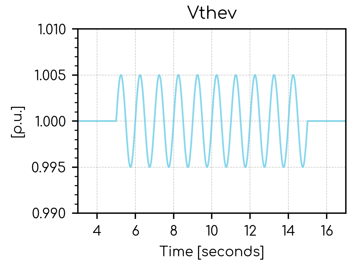
VOLT_OSCIL, START_T=5, END_T=15, MAG=0.005, FREQ=1, PSOMAG=2
If a VOLT_OSCIL Command is used, the Grid controls functionality is disabled within the same PSCAD™ Node.
Only one VOLT_OSCIL Command is supported in a single PSCAD™ Node.
When using the VOLT_OSCIL Command, you may observe that the magnitude (amplitude) of oscillation decreases with increasing oscillation frequency. This can be caused by low sampling frequency in any digital multimeter object/block which is measuring the RMS voltage using digital mode. The Frequency selection under Parameters may need to be set much higher (up to 1000 Hz, rather than 50 or 60 Hz) to produce a clean output oscillation signal. At higher sampling rates, the magnitude is now identical between frequencies.
The smiby built-in voltage multimeter has been configured for this purpose.
FREQ_OSCIL Command
FREQ_OSCIL, START_T=, END_T=, MAG=, FREQ=
Oscillates/modulates the frequency signal to the Thévenin equivalent source within the smiby block, using a sinusoidal waveform of amplitude MAG= at an oscillation frequency of FREQ=. The oscillation is enabled between START_T= seconds and END_T seconds from the start of the simulation.
Arguments:
- FREQ_OSCIL
- START_T 🔢 (
float): Time at which the oscillation starts during the dynamic simulation [s]. - END_T 🔢 (
float): Time at which the oscillation ends during the dynamic simulation [s]. - MAG 🔢 (
float): The amplitude of the frequency oscillation [Hz]. - FREQ 🔢 (
float): The frequency of the oscillation [Hz].
Only one FREQ_OSCIL Command is supported in a single PSCAD™ Node.
The FREQ_OSCIL Command is designed for low-frequency oscillations only (up to MAG=5 [Hz]).
Oscillations at a higher frequency may cause aliasing effects in digital multimeter objects and poor frequency tracking in on-line frequency (FFT) measurement devices inside smiby.
Example:
Assuming smiby is in the PSCAD™ Workspace, modulate the frequency of the Thévenin equivalent source starting at 5 seconds and ending at 15 seconds, with an amplitude of 0.5 [Hz] and frequency of 1 Hz as shown in the image below:
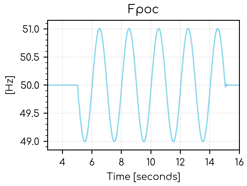
FREQ_OSCIL, START_T=5, END_T=15, MAG=0.5, FREQ=1
OUTPUT Command
The OUTPUT Command is used to output channels so they can be processed or displayed by a Plot node.
OUTPUT, [LOCATION=, INDEX=], TITLE=, [CHANNEL_TYPE=PQS, VALSCALE=, VAL_FUNCTION=, AT=], NAME=, [PLOT_STYLE=SOLID, DISPLAY_ONLY=NO, LEGEND=]
Outputs a variable from a PSCAD™ output channel block.
Arguments:
- OUTPUT
- LOCATION (
str)[Optional]: The component names, or component identifiers, defining the location of the output channel block within PSCAD™, separated by backslashes\. Use if there are multiple output channels which have the same name and identifier, but output different data and therefore you need to specify which one to output. This may occur when there are multiple instances of the same module. Defaults to no specific location and we will output the first output channel block found which matches theTITLE=Argument. - INDEX (
int)[Optional]: Used if multiple channels are being exported from a single PSCAD™ channel block. If not provided and multiple channels are being exported, an error will be raised (to ensure you are outputting the channel you expect). - TITLE (
str): The 'Title' field of the PSCAD™ output channel block to record. TheTitleis displayed in text under the output channel block in PSCAD™. - CHANNEL_TYPE (
str)[Optional]: The type of output channel. Specifying the correct value for the output channel will result in more accurate auto-scaling for connectedPlotNodes. Options:CHANNEL_TYPE=PQS: Active power [MW], reactive power [MVAr] or apparent power [MVA].CHANNEL_TYPE=V: Voltage [p.u.].CHANNEL_TYPE=F: Frequency [Hz].CHANNEL_TYPE=ANGLE: Angle [degrees].CHANNEL_TYPE=I: Current [p.u.], active current [p.u.] or reactive current [p.u.]CHANNEL_TYPE=BINARY: Binary outputs, such as LVRT/HVRT trigger flags.CHANNEL_TYPE=TAPRATIO: Transformer tap ratios [p.u.].CHANNEL_TYPE=PF: Power factor [unitless]. Click here for details on how gridmo calculates power factor.CHANNEL_TYPE=PU: Per unit [p.u.] (e.g. reference signals)
- VALSCALE 🔢 (
float)[Optional]: Multiplicative scaling factor applied to the output value (i.e. scaled_output =VALxVALSCALE). Default value is 1. - VAL_FUNCTION 🔢 (
str)[Optional]: Function applied to the output value(s). For example,VAL_FUNCTION=2*VAL+1. Cannot be used in conjunction withVALSCALE. Click here for more information on VAL_FUNCTION syntax and supported functions. - AT (
float)[Optional]: Time in the simulation [s] to extract a single value—the first sample at or after that time. IfAT=is omitted, the output is a time-series channel of values. Options:AT=x🔢 wherexis afloatAT=SIM_STARTAT=SIM_END
- NAME (
str): Output name. Output names must be unique within a Node. - PLOT_STYLE (
str)[Optional]: How this output channel should be plotted on connected Plot Nodes. Defaults toTYPE=SOLID. Options:TYPE=SOLID: A solid line.TYPE=DASHED: A dashed line.
- DISPLAY_ONLY (
bool)[Optional]: IfYES, calculations (such asSETTLING_TIME) will not be performed using this output channel. Default value isNO. - LEGEND (
str)[Optional]: Subplot legend name. Default value is no legend name. VAL(str)[Optional]: Deprecated. UseCHANNEL_TYPEinstead.
Example: Output the channel below and name the channel i_p_at_poc for use by other Nodes, such as a Plot Node.

OUTPUT, TITLE=P_POC, VAL=PQS, NAME=i_p_at_poc
Example: Same channel, but export only the final time-step value as a single Internode Variable.
OUTPUT, TITLE=P_POC, VAL=PQS, NAME=i_p_at_poc_final, AT=SIM_END
Example: Output the channel below which is connected to a wind turbine's high voltage ride-through flag output. Name the channel i_hvrt_flag for use by other Nodes, such as a Plot Node.

OUTPUT, TITLE=WTG_FRT_HV, VAL=BINARY, NAME=i_hvrt_flag
Example: My PSCAD™ case file has two aggregated inverter modules which are identical since they are two copies of the same PSCAD™ module. The first inverter module has a Name property =Inverter1 and the second inverter module has a Name property =Inverter2. Inside these inverter modules is a solar inverter control model which does not have a Name property - however its component id is 3542392321. I want to record the V_terminal channel from inside the solar inverter control model for both of the aggregated inverters (a total of two channels).
OUTPUT, TITLE=V_terminal, VAL=V, NAME=i_inverter_1_voltage, LOCATION=Inverter1\3542392321
OUTPUT, TITLE=V_terminal, VAL=V, NAME=i_inverter_2_voltage, LOCATION=Inverter2\3542392321
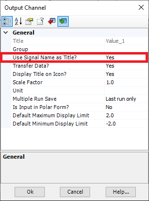
gridmo uses the 'Title' field of the PSCAD™ output channel block (even if it is greyed out). Depending on the PSCAD™ file configuration, selecting "Use Signal Name as Title?" as "Yes" may not always insert the desired Title. Please double check that the 'Title' parameter value is as expected.
Any PSCAD™ output channels not defined by an OUTPUT Command will not be recorded by PSCAD™. You must specify all required output channels.
OUTPUT_FUNCTION Command
OUTPUT_FUNCTION, FUNCTION=, [CHANNEL_TYPE=, AT=], NAME=, [PLOT_STYLE=SOLID, DISPLAY_ONLY=NO, LEGEND=]
Use OUTPUT_FUNCTION when you want to create an output that combines other previously defined outputs within the same Node.
See Math operations for more information on the supported functions.
Arguments:
- OUTPUT_FUNCTION
- FUNCTION (
str): User-defined function. - CHANNEL_TYPE (
str)[Optional]: The type of output channel. Specifying the correct value for the output channel will result in more accurate auto-scaling for connectedPlotNodes. Options:CHANNEL_TYPE=PQS: Active power [MW], reactive power [MVAr] or apparent power [MVA].CHANNEL_TYPE=V: Voltage [p.u.].CHANNEL_TYPE=F: Frequency [Hz].CHANNEL_TYPE=ANGLE: Angle [degrees].CHANNEL_TYPE=I: Current [p.u.], active current [p.u.] or reactive current [p.u.]CHANNEL_TYPE=BINARY: Binary outputs, such as LVRT/HVRT trigger flags.CHANNEL_TYPE=TAPRATIO: Transformer tap ratios [p.u.].CHANNEL_TYPE=PF: Power factor [unitless]. Click here for details on how gridmo calculates power factor.CHANNEL_TYPE=PU: Per unit [p.u.] (e.g. reference signals)
- AT (
float)[Optional]: Time in the simulation [s] to extract a single value—the first sample at or after that time. IfAT=is omitted, the output is a time-series channel of values. Options:AT=x🔢 wherexis afloatAT=SIM_STARTAT=SIM_END
- NAME (
str): Output name. Output names must be unique within a Node. - PLOT_STYLE (
str)[Optional]: How this output channel should be plotted on connected Plot Nodes. Defaults toTYPE=SOLID. Options:TYPE=SOLID: A solid line.TYPE=DASHED: A dashed line.
- DISPLAY_ONLY (
bool)[Optional]: IfYES, calculations (such asSETTLING_TIME) will not be performed using this output channel. Default value isNO. - LEGEND (
str)[Optional]: Subplot legend name. Default value is no legend name.
Example: Calculate the sum of the active power from two lines and name the output i_p_line_sum.
OUTPUT, TITLE=P_POC, VAL=PQS, NAME=i_p_line1
OUTPUT, TITLE=P_OTHER_LINE, VAL=PQS, NAME=i_p_line2

OUTPUT_FUNCTION, FUNCTION={{i_p_line1}}+{{i_p_line2}}, NAME=i_p_line_sum
Advanced Parameters
Each Advanced Parameter is entered on its own line as name=value.
Example: Set the simulation time step to 50 [µs], the plot step to 250 [µs], and ignore errors at simulation end.
sim.timestep=50
sim.plotstep=250
ignore.errors.at.sim.end=Yes
sim.timestep
- Description: Simulation time step (DELT).
- Type:
float - Units: [µs]
- Default: Setting as per the PSCAD™ model.
- Range: > 0
sim.timestep=value
sim.plotstep
- Description: Simulation plot step (the resolution to output to plot channels).
- Type:
float - Units: [µs]
- Default: Setting as per the PSCAD™ model.
- Range: > 0
sim.plotstep=value
sim.frequency.network.dependence
- Description: Network frequency dependence. If disabled, capacitive and inductive reactance are modelled as fixed values regardless of system frequency.
- Type:
bool - Units: N/A
- Default: No
- Range: Yes, No
Enabling network frequency dependence may cause unexpected behavior for some SMIB studies. For example, system voltage may vary during a frequency ramp test.
sim.frequency.network.dependence=value
sim.store.feed.forward.sigs
- Description: Store signals in local memory to view using tooltips. Defaults to the setting as per the PSCAD™ case file.
- Type:
bool - Units: N/A
- Default: Do not change (use setting as per PSCAD™ case file)
- Range: Yes, No
sim.store.feed.forward.sigs=value
ignore.errors.at.sim.end
- Description: Ignore any errors raised by PSCAD or EMTDC if the simulation is completed.
- Type:
bool - Units: N/A
- Default: No
- Range: Yes, No
ignore.errors.at.sim.end=value
never.emtdc.direct.launch
- Description: Do not launch this simulation using direct (EMTDC) launch mode, regardless of what the engine config is set to.
- Type:
bool - Units: N/A
- Default: No
- Range: Yes, No
never.emtdc.direct.launch=value
sim.snapshot.file
Deprecated. Use Initialize from snapshot instead.
- Description: If a relative file path to a PSCAD™
.snpfile is provided, initialise the PSCAD model using this snapshot file. - Type:
str - Units: N/A
- Default: Blank (do not use snapshot)
- Range: Valid snapshot files in the Inputs directory
sim.snapshot.file=value