DSATools™ PSAT
Introduction
The DSATools™ PSAT Node performs static study simulations which are powered by Powerflow & Short circuit Assessment Tool (PSAT), a 3rd party power systems software developed by Powertech Labs.
This Node is typically used for the following:
- Completing static studies (e.g. investigating thermal loading of an asset pre and post a variety of contingencies).
- Setting up cases for dynamic studies (e.g. creating a case for a specific active power set point as part of a test).
Check our system requirements page for information on which PSAT versions are currently supported.
User inputs
Select model
Model
Defines the input directory and file name of the PSAT Powerflow Binary file, including the .pfb file extension.
Example:
sunny-solar-farm\SMIB.pfb
File paths are relative to the Engine's 'inputs' directory, as defined by the Engine configuration parameter dirs.inputs. For example, if dirs.inputs was set as C:\Users\johnsmith\gridmo\Inputs\:
| Absolute file path | Relative file path (required by gridmo) |
|---|---|
| C:\Users\johnsmith\gridmo\Inputs\sunny-solar-farm\SMIB.pfb | sunny-solar-farm\SMIB.pfb |
Define simulation
Commands
Defines the Commands which configure the static simulation.
Supported Commands:
- ADD: Adds a new type of network element (e.g. generator, load).
- SET: Sets the status or value of a network element (e.g. bus, line, generator).
- SCALE_TX: Scales a single transformer's base power, used to simulate a variable number of aggregated transformers.
- CONTROL_XX: Controls a network element.
- SOLVE: Solves the static case, considering all previous
SETandCONTROLCommands. - OUTPUT: Outputs a value as an Internode Variable.
Advanced
PSAT version
Defines the PSAT version used for the Node. Defaults to Engine configuration.
See here for details on how to specify a partial version.
Advanced Parameters
Advanced Parameters allow users to configure test details which are not commonly used. Advanced Parameters are often specific to each Node type.
Each line represents a new Advanced Parameter and is entered as a=b format, where a is the name of the Parameter and b is the corresponding value. All Advanced Parameters are set to their default values if they are not included in the Advanced Parameters field.
Example: Set Advanced Parameter, sample.parameter to a value of 5.
sample.parameter=5
API Reference
This section details the Commands and Advanced Parameters specific to the Node.
Lines are defined using the following syntax: from->to#id.
When completing SMIB studies, we recommend the line points in the direction towards the bulk electrical grid (the to bus being closer to your Thévenin source) for easy interpretation of results.
ADD Command
Add generator
ADD, TYPE=GEN, BUS=, [GEN_ID], PMAX=, PMIN=, QMAX=, QMIN=, [MBASE=100, RSOURCE=0, XSOURCE=1.0]
Adds a generator network element at a specified bus.
Arguments:
- ADD
- TYPE (
str): Network element type. Set asGEN. - BUS (
int): Bus number. This bus number must existing within the case file. We will add the generator at this bus and change the bus type code to "2 - Generator Bus". - GEN_ID (
int)[Optional]: The ID of the newly created generator. If not provided, added generators have a PSAT ID ofxwherexis an integer (e.g. 100#1, 100#99). - PMAX 🔢 (
float): Maximum active power capability of the generator [MW]. - PMIN 🔢 (
float): Minimum active power capability of the generator [MW]. - QMAX 🔢 (
float): Maximum reactive power capability of the generator [MVAr]. - QMIN 🔢 (
float): Minimum reactive power capability of the generator [MVAr]. - MBASE 🔢 (
float)[Optional]: Base MVA of the generator [MVA]. Default value is 100. - RSOURCE 🔢 (
float)[Optional]: Generator resistance [p.u. on MBASE]. Default value is 0. - XSOURCE 🔢 (
float)[Optional]: Generator reactance [p.u. on MBASE]. Default value is 1.0.
By default, the generator dispatch conditions are set as the following:
- Generator terminal active power = 0 MW (i.e. Generator Properties -> MW Output = 0).
- Control mode is direct voltage control (i.e. Generator Properties -> Wind Machine -> MVAr Control Mode = "0 - N/A").
- Voltage control mode is set to terminal control, with the "Voltage", "Upper Limit" and "Lower Limit" set to the current bus voltage, such that the generator will inject Q=0 MVAr.
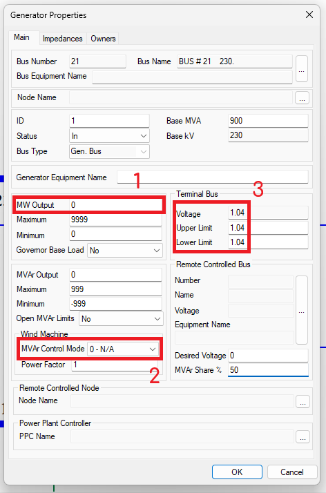
To change the generator dispatch conditions (e.g. Pgen, Qgen, Vref), please use the respective CONTROL_XX Commands.
gridmo will automatically change the bus to a type 2 (generator) bus if it is currently a type 1 (non-gen / load) bus in PSAT.
Example: Add a generator at bus 1000. The generator should have the following properties: Pmax = 100MW, Pmin = 20MW, Qmax = 30 MVAr, Qmin = -30MVAr.
ADD, TYPE=GEN, BUS=1000, PMAX=100, PMIN=20, QMAX=30, QMIN=-30
Add load
ADD, TYPE=LOAD, BUS=, P=, Q=
Adds a load network element at a specified bus.
Arguments:
- ADD
- TYPE (
str): Network element type. Set asLOAD. - BUS (
int): Bus number. This bus number must existing within the case file. - P 🔢 (
float): Constant active power [MW]. - Q 🔢 (
float): Constant reactive power [MVAr].
At least one of P= or Q= must be specified. Any unspecified values default to 0.
gridmo will set the PSAT 'Actual', 'Nominal' and 'Reference' fields (i.e. Load Properties -> Main) for active power and/or reactive power to same value as that specified in the Command.
Example: Add a 25 MW, 5 MVAr load at bus 400.
ADD, TYPE=LOAD, BUS=400, P=25, Q=5
Added loads have a PSAT ID of x where x is an integer. For example:
- The Command
ADD, BUS=100, P=10creates a load with identifier100#1. - If a second
ADD, BUS=100, P=10Command was used, a new load with identifier100#2would be created.
SET Command
Set bus
SET, BUS=, [BUS=], STATUS=
Sets the status of a bus.
Arguments:
- SET
- BUS (
int): Bus number. - BUS (
int)[Optional]: Additional bus numbers. - STATUS (
str): Bus status. Options:STATUS=OUT: Status is out of service.STATUS=1: Explicitly set bus type code as 1 (i.e. Load Bus).STATUS=2: Explicitly set bus type code as 2 (i.e. Gen Bus).STATUS=3: Explicitly set bus type code as 3 (i.e. Swing bus).STATUS=4: Explicitly set bus type code as 4 (i.e. Out of Service).
Example: Set bus 100 out of service.
SET, BUS=100, STATUS=OUT
Set line
SET, LINE=, [LINE=, STATUS=, SCR=, XR=]
Sets the status and impedance of a line.
Arguments:
- SET
- LINE (
pas): Line definition. Lines are defined using the following syntax:from->to#id. - LINE (
pas)[Optional]: Additional line definitions (only if usingSTATUS=, all other arguments only support one line) - STATUS (
str)[Optional]: Line status. Options:STATUS=IN: Status is in-service.STATUS=OUT: Status is out of service.
- SCR (
float)[Optional] Set the Short Circuit Ratio and X/R Ratio:SCR=X(whereXis a number): Sets the impedance of the given line to the equivalent Thévenin impedance based on the Project's rated active power [MW], the line voltage and the specified SCR and X/R ratio.SCR=INF: Sets the impedance of the given line to the minimum cross-software stable impedance.XR=Argument is ignored.
- XR 🔢 (
float)[Optional]: The reactance to resistance ratio to apply to the specified line. - R 🔢 (
float)[Optional]: Sets the resistance of the given line to the specified value in ohms. - X 🔢 (
float)[Optional]: Sets the reactance of the given line to the specified value in ohms. - B 🔢 (
float)[Optional]: Sets the charging susceptance of the given line to the specified value in microfarads (µF).
SCR and XR Arguments must be used together. These Arguments are typically only used in SMIB studies and are used to calculate the Thévenin equivalent source impedance of the infinite generator.
R, X, and B Arguments can be used independently or together to set specific line parameters in ohms and microfarads respectively. Not all three need to be specified.
Example: Set the impedance of the line from bus 800 to bus 900 which has an ID of 1. The line impedance should represent the system Thévenin equivalent impedance for an SCR of 3 and X/R ratio of 2.
SET, LINE=800->900#1, STATUS=IN, SCR=3, XR=2
Example: Set the impedance of the line from bus 1000 to bus 999 with ID 1 to near-zero impedance (infinite system strength).
SET, LINE=1000->999#1, STATUS=IN, SCR=INF, XR=1
Example: Set specific resistance, reactance and susceptance values for a line to model a collector group outage within a solar farm. Sets the line impedance to 0.2 + j1.3 ohms, with 4.7 uF of shunt capacitance.
SET, LINE=300->400#1, STATUS=IN, R=0.2, X=1.3, B=4.7
Set transformer
SET, TX=, [STATUS=, TAPRATIO=, WINDING=]
Sets the status of a transformer.
Arguments:
- SET
- TX (
pas): Transformer definition. Transformers are defined using the following syntax:bus1->bus2#id(two-winding fixed or adjustable transformer) orbus1->bus2->bus3#id(three-winding transformer). - STATUS (
str)[Optional]: Transformer status. If not specified, transformer status is not changed from the current state. Options:STATUS=IN: Status is in-service.STATUS=OUT: Status is out of service.
- TAPRATIO 🔢 (
float)[Optional]: Sets the tap ratio of the specified winding number. The control mode of the transformer will be set to "None" to ensure the set tap ratio is maintained irrespective of whetherSOLVE, LOCKTAPS=NOis used. - WINDING (
int)[Optional]: The winding number used when setting the tap ratio. Options:WINDING=1: The winding on the 'From' side of the transformer (or 'Primary' for three-winding) as specified on the 'Main' window for the transformer.WINDING=2: The winding on the 'To' side of the transformer (or 'Secondary' for three-winding) as specified on the 'Main' window for the transformer.WINDING=3: The 'Tertiary' winding of the three-winding transformer (only applicable for three-winding transformers).
The Engine will check that the specified tap ratio is valid given the transformer tap configuration.
If the transformer does not have a tap changer enabled, or the transformer's configuration does not allow the specified tap ratio, the Engine will raise an error.
Example: Set the three-winding transformer in-service which is located between bus 100, bus 200, and bus 300 and which has an ID of 1.
SET, TX=100->200->300#1, STATUS=IN
Example: Set the tap position of winding one of the two-winding transformer to 0.975 which is located between bus 100 and bus 200 and which has an ID of 1.
SET, TX=100->200#1, TAPRATIO=0.975, WINDING=1
Set generator
SET, GEN=, [GEN=], STATUS=, [PMAX=, PMIN=, QMAX=, QMIN=, MBASE=, VAL_FUNCTION=]
Sets the status or active/reactive power limits of a generator.
Arguments:
- SET
- GEN (
pas): Generator definition. Generators are defined using the following syntax:bus#id. - GEN (
pas)[Optional]: Additional generator definitions. - STATUS (
str): Generator status. Options:STATUS=IN: Status is in-service.STATUS=OUT: Status is out of service.
- PMAX 🔢 (
float)[Optional]: Maximum active power capability of the generator [MW]. - PMIN 🔢 (
float)[Optional]: Minimum active power capability of the generator [MW]. - QMAX 🔢 (
float)[Optional]: Maximum reactive power capability of the generator [MVAr]. - QMIN 🔢 (
float)[Optional]: Minimum reactive power capability of the generator [MVAr]. - MBASE 🔢 (
float)[Optional]: Base MVA of the generator [MVA]. - VAL_FUNCTION 🔢 (
str)[Optional]: Function applied toQMAX,QMIN,PMAX,PMINandMBASE. For example,VAL_FUNCTION=2*VAL+1. Click here for more information on VAL_FUNCTION syntax and supported functions.
- Setting
PMIN=orPMAX=will clamp the active power (Pgen) of the generator to within the specified bounds. - Setting
QMIN=orQMAX=will clamp the reactive power (Qgen) of the generator to within the specified bounds.
Example: Set the generator out of service which is located at bus 100 which has an ID of 1.
SET, GEN=100#1, STATUS=OUT
Example: Set the aggregated generator at bus 150 with id 1 active power min and maximum range to -1.5 MW (for example, to represent a synchronous machine operating in synchronous condenser mode).
SET, GEN=150#1, PMAX=-1.5, PMIN=-1.5
Set load
SET, LOAD=, STATUS=
Sets the status of a load.
Arguments:
- SET
- LOAD (
pas): Load definition. Loads are defined using the following syntax:bus#id. - STATUS (
str): Load status. Options:STATUS=IN: Status is in-service.STATUS=OUT: Status is out of service.
Example: Set the load out of service which is located at bus 100 and which has an ID of 2.
SET, LOAD=100#2, STATUS=OUT
Set fixed or switched shunt
SET, SHUNT=, STATUS=
Sets the status of a switched or fixed shunt.
Arguments:
- SET
- SHUNT or FSHUNT (
pas): Shunt definition, automatically selects between switched or fixed shunt based on shunts present in the model. Use the following syntax:bus#id. See below for details. - STATUS (
str): Shunt status. Options:STATUS=IN: Status is in-service.STATUS=OUT: Status is out of service.
PSAT supports two different types of shunts, a fixed type and a switched type.
gridmo will attempt to automatically determine which shunt is being requested as follows:
- If there is a switched shunt on the specified bus with the specified ID, it will be set by this command..
- Otherwise, if there is a fixed shunt on the specified bus with the specified ID, it will be set by this command
If there is both a switched and a fixed shunt on the same bus with the same ID, you can force gridmo to only consider fixed shunts by replacing SHUNT= with FSHUNT= in your command (though we don't recommend mixing fixed and switched shunts on the same bus in general.)
Example: Bus 200 has a single switched shunt present, set that shunt out of service.
SET, SHUNT=200#1, STATUS=OUT
Example: Bus 200 has two fixed shunts present (with IDs 1 and 2) and no switched shunt present, set the second fixed shunt out of service.
SET, SHUNT=200#2, STATUS=OUT
Example: Bus 200 has both a switched and fixed shunt (both with ID 1), set the fixed shunt out of service, leaving the switched shunt in service.
// Use FSHUNT= here to force gridmo to only modify fixed shunts
SET, FSHUNT=200#1, STATUS=OUT
SCALE_TX Command
SCALE_TX, [TX=], CHANGE=
Applies an absolute or relative scaling factor to one or more transformers. Typically used to simulate a variable number of aggregated transformers.
Arguments:
- SCALE_TX
- TX (
pas): Transformer definition. Transformers are defined using the following syntax:bus1->bus2#id(two-winding transformer) orbus1->bus2->bus3#id(three-winding transformer). - TX (
pas)[Optional]: Additional transformer definition(s). - CHANGE: How to scale the specified transformers. Options:
- Absolute value 🔢 (
float): Reduce/increase the specified transformers equally by a fixed factor, such asCHANGE = -2meaning reduce each transformer's base value by2MVA. - Relative value (
float%): Apply a percentage scale to each transformer specified, such asCHANGE = -20%meaning reduce each transformer's base value by20%.
- Absolute value 🔢 (
Example: The transformer between buses 1225 and 1226 with ID 1 represents an aggregatation of 25 equivalent transformers as part of a SMIB model. Scale the transformer so it represents only a single aggregated transformer (for benchmarking purposes with site commissioning data).
SCALE_TX, TX=1225->1226#1, CHANGE=-96% // 1/25 = 0.04, so scale down by 96% to turn 25 transformers into 1
CONTROL Command
Control Commands are additional solution requirements added to the convergence algorithm which is initiated by the SOLVE Command. A SOLVE Command is required for preceding CONTROL Commands to be considered.
CONTROL Commands are an extension of the 'Power Plant Controller' functionality which is native within PSAT and they operate in a similar manner to each other. For example in PSAT, PPC properties can override generator properties (e.g. The midpoint of PPC properties Vdblow and Vdbhigh override the generator property desired voltage). In a similar manner, the Command CONTROL_P can override the generator property MW Output to achieved a desired active power at a remote line.
If you are using gridmo CONTROL commands to control a plant, please disable any native Power Plant Controllers (PPC) on the generators being controlled. This will avoid potential conflicts where both the gridmo CONTROL Commands and PSAT PPC functionality are both trying to control a generator.
CONTROL_P Active power from generator(s)
CONTROL_P, GEN=[DEFINITION=, PRIORITY=1, RATIO=], GEN=[...], [ATLINE=, METERBUS=, VAL_FUNCTION=], VAL=
Uses a software agonistic power plant controller to achieve an active power target. The target can be specified at the generator terminals, or at a remote line. Supports dispatch order and active power sharing (and a mixture of both).
Arguments
- CONTROL_P
- GEN (
object): Generator definition with parameters on a per-generator level within square brackets[...]:- DEFINITION (
pas): Generator definition. Generators are defined using the following syntax:bus#id. - PRIORITY 🔢 (
int)[Optional]:- Dispatch priority (order) for this generator. Only positive integers supported. Defaults to 1.
- Generators with the highest priority will be dispatched first as far as their operational limits allow, then generators in later orders are dispatched next.
- RATIO 🔢 (
float)[Optional]:- Sharing ratio for this generator. If
RATIO=0this generator will not contribute to achieving the target. Only values greater than or equal to zero supported. Defaults to generator base (in MVA). - Generators in the same
PRIORITYwill share the active power target based on theirRATIOvalues. - The engine will normalize all share values, so it can be ratios or percentages or pu etc.
- Sharing ratio for this generator. If
- DEFINITION (
- ATLINE Location of the target active power [Optional].
- If not specified, the active power target is regulated at the generator terminals.
- If
ATLINE=from->to#id(pas): Active power target is regulated across the specified line. Lines are defined using the following syntax:from->to#id.
- METERBUS (
int)[Optional]: Bus number which is the metering point for theATLINE=line. Default value is the 'from' bus number as per theATLINE=argument. - VAL_FUNCTION 🔢 (
str)[Optional]: Function applied toVAL. For example,VAL_FUNCTION=2*VAL+1. Click here for more information on VAL_FUNCTION syntax and supported functions. - VAL 🔢 (
float): Active power setpoint [MW].
Examples
Solar farm with single aggregated generator
- Control the aggregated generator at bus 100 with ID
1to achieve a target active power of95MW at the point of connection, between bus 400 and bus 500 with branch ID1.
CONTROL_P, GEN=[DEFINITION=100#1], ATLINE=400->500#1, VAL=95
Solar farm with multiple aggregated generators
- Control the two aggregated generators at bus 100 with ID
1and bus 200 with ID2to achieve a target active power of95MW at the point of connection, between bus 400 and bus 500 with branch ID1. - The active power contribution from each generator should be shared equally.
CONTROL_P, GEN=[DEFINITION=100#1, RATIO=0.5], GEN=[DEFINITION=200#2, RATIO=0.5], ATLINE=400->500#1, VAL=95
Solar farm with multiple aggregated generators and priority dispatch
- Control the two aggregated generators at bus 100 with ID
1and bus 200 with ID2to achieve a target active power of95MW at the point of connection, between bus 400 and bus 500 with branch ID1. - The active power contribution from each generator should be shared equally.
- Prioritise supplying active power from the aggregated solar farm generator at bus 100 before supplying any active power from the aggregated BESS generator at bus 200.
CONTROL_P, GEN=[DEFINITION=100#1, PRIORITY=1], GEN=[DEFINITION=200#2, PRIORITY=2], ATLINE=400->500#1, VAL=95
Solar farm with multiple aggregated generators and unequal power sharing
- Control the two aggregated generators at bus 100 with ID
1and bus 200 with ID2to achieve a target active power of95MW at the point of connection, between bus 400 and bus 500 with branch ID1. - The active power contribution from each generator should be 70% from the aggregated solar farm generator at bus 100 and 30% from the aggregated solar farm generator at bus 200.
CONTROL_P, GEN=[DEFINITION=100#1, RATIO=70], GEN=[DEFINITION=200#2, RATIO=30], ATLINE=400->500#1, VAL=95
Large wind farm with multiple aggregated generators, power sharing based on relative size
- Control the four aggregated generators at buses 100, 101, 200 and 201 - all with ID
1. - Achieve an active power target of 760 MW at the point of connection, between bus 400 and bus 500 with branch ID
1. - The active power contribution from each generator should be shared equally based on the relative size of each generator.
CONTROL_P, GEN=[DEFINITION=100#1], GEN=[DEFINITION=101#1], GEN=[DEFINITION=200#1], GEN=[DEFINITION=201#1], ATLINE=400->500#1, VAL=760
CONTROL_VDROOP Voltage droop control from generator(s)
CONTROL_VDROOP, GEN=[DEFINITION=, PRIORITY=1, RATIO=], GEN=[...], QBASE=, DROOP%=, DEADBAND=, QMIN=, QMAX=, ATBUS=, [ATLINE=, METERBUS=, VAL_FUNCTION=], VAL=
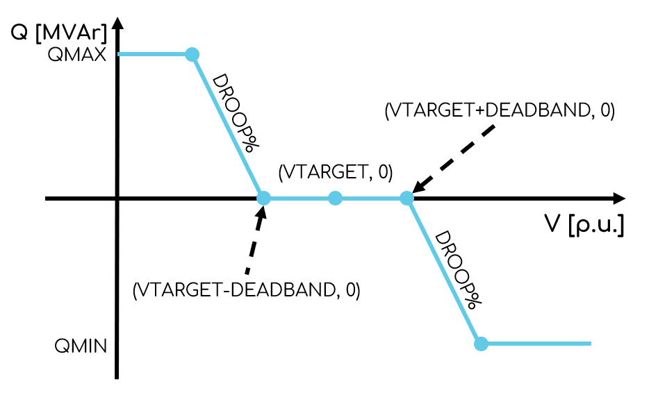
Uses a software agnostic power plant controller to achieve voltage droop control. Controls one or more generators using voltage droop control. If the measured voltage is larger/smaller than the voltage target + deadband, the specified generators will be controlled to absorb/supply reactive power equal to the droop percentage of QBASE for every 1% the measured voltage is above the voltage target + deadband.
Arguments
- CONTROL_VDROOP
- GEN (
object): Generator definition with parameters on a per-generator level within square brackets[...]:- DEFINITION (
pas): Generator definition. Generators are defined using the following syntax:bus#id. - PRIORITY 🔢 (
int)[Optional]:- Dispatch priority (order) for this generator. Only positive integers supported. Defaults to 1.
- Generators with the highest priority will be dispatched first as far as their operational limits allow, then generators in later orders are dispatched next.
- RATIO 🔢 (
float)[Optional]:- Sharing ratio for this generator. If
RATIO=0this generator will not contribute to achieving the target. Only values greater than or equal to zero supported. Defaults to generator base (in MVA). - Generators in the same
PRIORITYwill share the reactive power target based on theirRATIOvalues. - The engine will normalize all share values, so it can be ratios or percentages or pu etc.
- Sharing ratio for this generator. If
- DEFINITION (
- QBASE 🔢 (
float): Base reactive power [MVAr]. - DROOP% (
float): Droop percentage [%]. - DEADBAND 🔢 (
float): Voltage deadband [p.u.]. - QMIN 🔢 (
float)[Optional]: Minimum reactive power limit at theATLINE=line [MVAr]. Default value is negative infinity. - QMAX 🔢 (
float)[Optional]: Maximum reactive power limit at theATLINE=line [MVAr]. Default value is positive infinity. - ATBUS (
int): Bus number which has the target voltage. - ATLINE (
pas)[Optional]: Line which is used for measuring the reactive power. Lines are defined using the following syntax:from->to#id. - METERBUS (
int)[Optional]: Bus number which is the metering point for theATLINE=line. Default value is the 'from' bus number as per theATLINE=argument. - VAL_FUNCTION 🔢 (
str)[Optional]: Function applied toVAL. For example,VAL_FUNCTION=2*VAL+1. Click here for more information on VAL_FUNCTION syntax and supported functions. - VAL 🔢 (
float): Target voltage set point [p.u.].
Examples
Single generator voltage droop control
- Control a generator at bus 100 with ID
1using voltage droop control with a target voltage of1.01p.u. at bus 600, a QBASE of50MVAr, a droop percentage of4%and a voltage deadband of0.01p.u. The reactive power is measured at the line between bus 600 and bus 700 with branch ID1.
CONTROL_VDROOP, GEN=[DEFINITION=100#1], QBASE=50, DROOP%=4, DEADBAND=0.01, ATBUS=600, ATLINE=600->700#1, VAL=1.01
Multiple generators with equal sharing
- Control two generators at bus 100 with ID
1and bus 200 with ID1using voltage droop control. The generators have equal machine base and represent two aggregated collector groups of a wind farm. Target voltage of1.01p.u. at bus 600, QBASE of50MVAr, droop percentage of4%and voltage deadband of0.01p.u. The static controller logic should not consider existing dispatch files and should ensure reactive power dispatch is shared equally.
CONTROL_VDROOP, GEN=[DEFINITION=100#1, RATIO=0.5], GEN=[DEFINITION=200#1, RATIO=0.5], QBASE=50, DROOP%=4, DEADBAND=0.01, ATBUS=600, ATLINE=600->700#1, VAL=1.01
Multiple generators with priority dispatch
- Control two generators with priority dispatch where the solar farm generator at bus 100 is prioritised before the BESS generator at bus 200. Target voltage of
1.0p.u. at bus 500, QBASE of100MVAr, droop percentage of5%and voltage deadband of0.02p.u.
CONTROL_VDROOP, GEN=[DEFINITION=100#1, PRIORITY=1], GEN=[DEFINITION=200#1, PRIORITY=2], QBASE=100, DROOP%=5, DEADBAND=0.02, ATBUS=500, ATLINE=500->600#1, VAL=1.0
Multiple generators with unequal power sharing
- Control two generators with unequal sharing where 70% of reactive power comes from the generator at bus 100 and 30% from the generator at bus 200. Target voltage of
1.02p.u. at bus 400, QBASE of75MVAr, droop percentage of3%and voltage deadband of0.015p.u.
CONTROL_VDROOP, GEN=[DEFINITION=100#1, RATIO=70], GEN=[DEFINITION=200#1, RATIO=30], QBASE=75, DROOP%=3, DEADBAND=0.015, ATBUS=400, ATLINE=400->500#1, VAL=1.02
Large wind farm with multiple generators and reactive power limits
- Control four generators at buses 100, 101, 200 and 201 (all with ID
1) with reactive power limits. Target voltage of1.0p.u. at bus 300, QBASE of200MVAr, droop percentage of6%, voltage deadband of0.01p.u., minimum reactive power limit of-150MVAr and maximum reactive power limit of150MVAr.
CONTROL_VDROOP, GEN=[DEFINITION=100#1], GEN=[DEFINITION=101#1], GEN=[DEFINITION=200#1], GEN=[DEFINITION=201#1], QBASE=200, DROOP%=6, DEADBAND=0.01, QMIN=-150, QMAX=150, ATBUS=300, ATLINE=300->400#1, VAL=1.0
CONTROL_VDIRECT Direct voltage control from generator(s)
CONTROL_VDIRECT, GEN=, GEN=..., ATBUS=, [VAL_FUNCTION=], VAL=
Controls one or more generators using direct voltage control (not voltage droop control). CONTROL_VDIRECT is a simpler command compared to the others.
Arguments
- CONTROL_VDIRECT
- GEN (
pas): Generator definition. Generators are defined using the following syntax:bus#id. - GEN (
pas)[Optional]: Additional generator definitions. Generators are defined using the following syntax:bus#id. - ATBUS (
int): Bus number which has the target voltage. - VAL_FUNCTION 🔢 (
str)[Optional]: Function applied toVAL. For example,VAL_FUNCTION=2*VAL+1. Click here for more information on VAL_FUNCTION syntax and supported functions. - VAL 🔢 (
float): Target voltage set point [p.u.].
Basic direct voltage control
- Control the generator at bus 100 with ID
1. The control is direct voltage control of bus 300 with a target voltage of1.01p.u.
CONTROL_VDIRECT, GEN=100#1, ATBUS=300, VAL=1.01
Multiple generator voltage control
- Control two generators at bus 100 with ID
1and bus 200 with ID1using direct voltage control. The control is direct voltage control of bus 300 with a target voltage of1.03p.u.
CONTROL_VDIRECT, GEN=100#1, GEN=200#1, ATBUS=300, VAL=1.03
CONTROL_Q Reactive power from generator(s)
CONTROL_Q, GEN=[DEFINITION=, PRIORITY=1, RATIO=], GEN=[...], [ATLINE=, METERBUS=, VAL_FUNCTION=], VAL=
Uses a software agonistic power plant controller to achieve a reactive power target. The target can be specified at the generator terminals, or at a remote line. Supports dispatch order and reactive power sharing (and a mixture of both).
Arguments
- CONTROL_Q
- GEN (
object): Generator definition with parameters on a per-generator level within square brackets[...]:- DEFINITION (
pas): Generator definition. Generators are defined using the following syntax:bus#id. - PRIORITY 🔢 (
int)[Optional]:- Dispatch priority (order) for this generator. Only positive integers supported. Defaults to 1.
- Generators with the highest priority will be dispatched first as far as their operational limits allow, then generators in later orders are dispatched next.
- RATIO 🔢 (
float)[Optional]:- Sharing ratio for this generator. If
RATIO=0this generator will not contribute to achieving the target. Only values greater than or equal to zero supported. Defaults to generator base (in MVA). - Generators in the same
PRIORITYwill share the reactive power target based on theirRATIOvalues. - The engine will normalize all share values, so it can be ratios or percentages or pu etc.
- Sharing ratio for this generator. If
- DEFINITION (
- ATLINE Location of the target reactive power [Optional].
- If not specified, the reactive power target is regulated at the generator terminals.
- If
ATLINE=from->to#id(pas): Reactive power target is regulated across the specified line. Lines are defined using the following syntax:from->to#id.
- METERBUS (
int)[Optional]: Bus number which is the metering point for theATLINE=line. Default value is the 'from' bus number as per theATLINE=argument. - VAL_FUNCTION 🔢 (
str)[Optional]: Function applied toVAL. For example,VAL_FUNCTION=2*VAL+1. Click here for more information on VAL_FUNCTION syntax and supported functions. - VAL 🔢 (
float): Reactive power setpoint [MVAr].
Examples
Solar farm with single aggregated generator
- Control the aggregated generator at bus 100 with ID
1to achieve a target reactive power of0MVAr at the point of connection, between bus 400 and bus 500 with branch ID1.
CONTROL_Q, GEN=[DEFINITION=100#1], ATLINE=400->500#1, VAL=0
Solar farm with multiple aggregated generators
- Control the two aggregated generators at bus 100 with ID
1and bus 200 with ID2to achieve a target reactive power of0MVAr at the point of connection, between bus 400 and bus 500 with branch ID1. - The reactive power contribution from each generator should be shared equally.
CONTROL_Q, GEN=[DEFINITION=100#1, RATIO=0.5], GEN=[DEFINITION=200#2, RATIO=0.5], ATLINE=400->500#1, VAL=0
Solar farm with multiple aggregated generators and priority dispatch
- Control the two aggregated generators at bus 100 with ID
1and bus 200 with ID2to achieve a target reactive power of0MVAr at the point of connection, between bus 400 and bus 500 with branch ID1. - The reactive power contribution from each generator should be shared equally.
- Prioritise supplying reactive power from the aggregated solar farm generator at bus 100 before supplying any reactive power from the aggregated BESS generator at bus 200.
CONTROL_Q, GEN=[DEFINITION=100#1, PRIORITY=1], GEN=[DEFINITION=200#2, PRIORITY=2], ATLINE=400->500#1, VAL=0
Solar farm with multiple aggregated generators and unequal power sharing
- Control the two aggregated generators at bus 100 with ID
1and bus 200 with ID2to achieve a target reactive power of0MVAr at the point of connection, between bus 400 and bus 500 with branch ID1. - The reactive power contribution from each generator should be 70% from the aggregated solar farm generator at bus 100 and 30% from the aggregated solar farm generator at bus 200.
CONTROL_Q, GEN=[DEFINITION=100#1, RATIO=70], GEN=[DEFINITION=200#2, RATIO=30], ATLINE=400->500#1, VAL=0
Large wind farm with multiple aggregated generators, power sharing based on relative size
- Control the four aggregated generators at buses 100, 101, 200 and 201 - all with ID
1. - Achieve a reactive power target of
0MVAr at the point of connection, between bus 400 and bus 500 with branch ID1. - The reactive power contribution from each generator should be shared equally based on the relative size of each generator.
CONTROL_Q, GEN=[DEFINITION=100#1], GEN=[DEFINITION=101#1], GEN=[DEFINITION=200#1], GEN=[DEFINITION=201#1], ATLINE=400->500#1, VAL=0
CONTROL_PF - Control generator(s) power factor
CONTROL_PF, GEN=[DEFINITION=, PRIORITY=1, RATIO=], GEN=[...], [ATLINE=, METERBUS=, VAL_FUNCTION=], VAL=
Uses a software agonistic power plant controller to achieve a power factor target. The target can be specified at the generator terminals, or at a remote line. Supports dispatch order and power factor control sharing (and a mixture of both).
Arguments
- CONTROL_PF
- GEN (
object): Generator definition with parameters on a per-generator level within square brackets[...]:- DEFINITION (
pas): Generator definition. Generators are defined using the following syntax:bus#id. - PRIORITY 🔢 (
int)[Optional]:- Dispatch priority (order) for this generator. Only positive integers supported. Defaults to 1.
- Generators with the highest priority will be dispatched first as far as their operational limits allow, then generators in later orders are dispatched next.
- RATIO 🔢 (
float)[Optional]:- Sharing ratio for this generator. If
RATIO=0this generator will not contribute to achieving the target. Only values greater than or equal to zero supported. Defaults to generator base (in MVA). - Generators in the same
PRIORITYwill share the reactive power target based on theirRATIOvalues. - The engine will normalize all share values, so it can be ratios or percentages or pu etc.
- Sharing ratio for this generator. If
- DEFINITION (
- ATLINE Location of the target power factor [Optional].
- If not specified, the power factor target is regulated at the generator terminals.
- If
ATLINE=from->to#id(pas): Power factor target is regulated across the specified line. Lines are defined using the following syntax:from->to#id.
- METERBUS (
int)[Optional]: Bus number which is the metering point for theATLINE=line. Default value is the 'from' bus number as per theATLINE=argument. - VAL_FUNCTION 🔢 (
str)[Optional]: Function applied toVAL. For example,VAL_FUNCTION=2*VAL+1. Click here for more information on VAL_FUNCTION syntax and supported functions. - VAL 🔢 (
float): Power factor setpoint. Using generator convention, positive power factor means injecting reactive power. Range is from -1.0 to 1.0.
Examples
Solar farm with single aggregated generator
- Control the aggregated generator at bus 100 with ID
1to achieve a target power factor of0.95(injecting reactive power) at the point of connection, between bus 400 and bus 500 with branch ID1.
CONTROL_PF, GEN=[DEFINITION=100#1], ATLINE=400->500#1, VAL=0.95
Solar farm with multiple aggregated generators
- Control the two aggregated generators at bus 100 with ID
1and bus 200 with ID2to achieve a target power factor of1.0(unity) at the point of connection, between bus 400 and bus 500 with branch ID1. - The power factor control contribution from each generator should be shared equally.
CONTROL_PF, GEN=[DEFINITION=100#1, RATIO=0.5], GEN=[DEFINITION=200#2, RATIO=0.5], ATLINE=400->500#1, VAL=1.0
Solar farm with multiple aggregated generators and priority dispatch
- Control the two aggregated generators at bus 100 with ID
1and bus 200 with ID2to achieve a target power factor of0.98(injecting reactive power) at the point of connection, between bus 400 and bus 500 with branch ID1. - The power factor control contribution from each generator should be shared equally.
- Prioritise supplying reactive power from the aggregated solar farm generator at bus 100 before supplying any reactive power from the aggregated BESS generator at bus 200.
CONTROL_PF, GEN=[DEFINITION=100#1, PRIORITY=1], GEN=[DEFINITION=200#2, PRIORITY=2], ATLINE=400->500#1, VAL=0.98
Solar farm with multiple aggregated generators and unequal power sharing
- Control the two aggregated generators at bus 100 with ID
1and bus 200 with ID2to achieve a target power factor of0.95(injecting reactive power) at the point of connection, between bus 400 and bus 500 with branch ID1. - The power factor control contribution from each generator should be 70% from the aggregated solar farm generator at bus 100 and 30% from the aggregated solar farm generator at bus 200.
CONTROL_PF, GEN=[DEFINITION=100#1, RATIO=70], GEN=[DEFINITION=200#2, RATIO=30], ATLINE=400->500#1, VAL=0.95
Large wind farm with multiple aggregated generators, power sharing based on relative size
- Control the four aggregated generators at buses 100, 101, 200 and 201 - all with ID
1. - Achieve a power factor target of
-0.95(absorbing reactive power) at the point of connection, between bus 400 and bus 500 with branch ID1. - The power factor control contribution from each generator should be shared equally based on the relative size of each generator.
CONTROL_PF, GEN=[DEFINITION=100#1], GEN=[DEFINITION=101#1], GEN=[DEFINITION=200#1], GEN=[DEFINITION=201#1], ATLINE=400->500#1, VAL=-0.95
SOLVE Command
SOLVE, [LOCKTAPS=, LOCKSHUNTS=]
Solves the static case, considering all previous SET and CONTROL Commands. CONTROL Commands are achieved by solving the static case, observing the monitored buses/lines (e.g. ATLINE=), comparing the observed value with the desired value and tolerance limits, adjusting the controlled elements (e.g. GEN=) if required and repeating this process as required.
Arguments:
- SOLVE
- LOCKTAPS (
str)[Optional]: Solution option specifying whether the position of transformer taps may change during the solution. Defaults toNO. Options:LOCKTAPS=YES: Transformer taps are locked.LOCKTAPS=NO: Transformer taps are unlocked.
- LOCKSHUNTS (
str)[Optional]: Solution option specifying whether the position of switched shunts may change during the solution. Defaults toNO. Options:LOCKSHUNTS=YES: Switched shunt positions are locked.LOCKSHUNTS=NO: Switched shunt positions are unlocked (discrete shunt steps).
All SET, SCALE_TX and CONTROL Commands preceding a SOLVE Command are applied at the same time when the SOLVE Command is used. Multiple SOLVE Commands are supported and can be used when you want to apply SET and CONTROL Commands sequentially. For example:
SET, ...<1>...
SET, ...<2>...
CONTROL, ...<1>...
SOLVE
CONTROL, ...<2>...
SOLVE
This following two static solves will occur:
- Solve considering
SET COMMAND 1,SET COMMAND 2andCONTROL COMMAND 1; then - Solve considering
CONTROL COMMAND 2.
Example: Solve the case where transformer taps are not locked and where switched shunt positions are locked.
SOLVE, LOCKTAPS=NO, LOCKSHUNTS=YES
OUTPUT Command
Only one value can be output per OUTPUT Command.
The Node automatically outputs .pfb files ready for use by connected DSATools™ TSAT Nodes. Therefore, you don't need to specify this output.
Output bus value
OUTPUT, BUS=, VAL=, [VAL_FUNCTION=], NAME=
Outputs a value from a bus.
Arguments:
- OUTPUT
- BUS (
int): Bus number. - VAL (
str): Bus value. Options:VAL=V: Voltage [p.u.].VAL=VKV: Voltage [kV].VAL=ANGLE: Angle [degrees].
- VAL_FUNCTION 🔢 (
str)[Optional]: Function applied to the output value(s). For example,VAL_FUNCTION=2*VAL+1. Click here for more information on VAL_FUNCTION syntax and supported functions. - NAME (
str): Output name. Output names must be unique within a Node.
Example: Output the voltage [p.u] at bus 100 and name the Internode Variable 'busvolts'.
OUTPUT, BUS=100, VAL=V, NAME=i_busvolts
Output line value
OUTPUT, LINE=, VAL=, [RATING_NUMBER=, METERBUS=, VAL_FUNCTION=], NAME=
Outputs a value from a line.
Arguments:
- OUTPUT
- LINE (
pas): Line definition. Lines are defined using the following syntax:from->to#id. Values are output at the 'from-side' of the line. - VAL (
str): Line value. Options:VAL=P: Active power [MW].VAL=Q: Reactive power [MVAr].VAL=S: Apparent power [MVA].VAL=PF: Power factor (generator convention,P/S) [unitless]. Click here for details on how gridmo calculates power factor.VAL=LOAD%: Thermal loading using the 'Rating 1' field [%].VAL=RATING: Line rating [MVA]. RequiresRATING_NUMBER=to be specified.
- RATING_NUMBER (
int)[Optional]: Rating number to be output (e.g.1). Only required ifVAL=RATING. - METERBUS (
int)[Optional]: Bus number which is the metering point for theLINE=line. Default value is the 'from' bus number as per theLINE=argument. - VAL_FUNCTION 🔢 (
str)[Optional]: Function applied to the output value(s). For example,VAL_FUNCTION=2*VAL+1. Click here for more information on VAL_FUNCTION syntax and supported functions. - NAME (
str): Output name. Output names must be unique within a Node.
Example: Output the active power flowing through the line from bus 100 to bus 200 (measured at the 'from-side') which has an ID of 1. Name the Internode Variable 'p_at_line'.
OUTPUT, LINE=100->200#1, VAL=P, NAME=i_p_at_line
Output transformer value
OUTPUT, TX=, VAL=, [RATING_NUMBER=, WINDING=, METERBUS=, VAL_FUNCTION=], NAME=
Outputs a value from a transformer.
Arguments:
- OUTPUT
- TX (
pas): Transformer definition. Transformers are defined using the following syntax:bus1->bus2#id(two-winding transformer) orbus1->bus2->bus3#id(three-winding transformer). - VAL (
str): Transformer value. Options:VAL=P: Active power [MW].VAL=Q: Reactive power [MVAr].VAL=S: Apparent power [MVA].VAL=PF: Power factor (generator convention,P/S) [unitless]. Click here for details on how gridmo calculates power factor.VAL=TAPRATIO: Tap ratio of the winding with the highest base voltage - as this is most likely where the tap changer is present (decimal, such as 0.90 meaning 90% of default tap) [unitless].VAL=LOAD%: Thermal loading using the 'RATE1' field [%].VAL=RATING: Transformer rating [MVA]. RequiresRATING_NUMBER=to be specified. RequiresWINDING=to be specified for three-winding transformers.
- RATING_NUMBER (
int)[Optional]: Rating number to be output (e.g.1). Only required ifVAL=RATING. - WINDING (
int)[Optional]: Winding number for outputting transformer rating. Only required ifVAL=RATINGand the transformer has three-windings. - METERBUS (
int)[Optional]: Bus number which is the metering point for theTX=line. Default value is the 'from' bus number as per theTX=argument. Not supported for three-winding transformers. - VAL_FUNCTION 🔢 (
str)[Optional]: Function applied to the output value(s). For example,VAL_FUNCTION=2*VAL+1. Click here for more information on VAL_FUNCTION syntax and supported functions. - NAME (
str): Output name. Output names must be unique within a Node.
The OUTPUT, TX= Command has limited support for three-winding transformers. Specifically, measuring power flow through a three-winding transformer is not recommended as, in this gridmo Command, it is ambiguous where the metering is occurring.
Using METERBUS= is not supported for three-winding transformers as it is unclear what direction to assign to 'positive' power flow - for more information see Error 114.
If you need to monitor a three-winding transformer, please consider instead using a 'dummy' line (a line with zero impedance) and monitoring that line.
Example: Output the apparent power flowing through the transformer located between bus 100 to bus 200 which has an ID of 2. Name the Internode Variable i_tx_sload.
OUTPUT, TX=100->200#2, VAL=S, NAME=i_tx_sload
Output generator value
OUTPUT, GEN=, VAL=, [VAL_FUNCTION=], NAME=
Outputs a value from a generator.
Arguments:
- OUTPUT
- GEN (
pas): Generator definition. Generators are defined using the following syntax:bus#id. - VAL (
str): Generator value. Options:VAL=P: Active power [MW].VAL=Q: Reactive power [MVAr].VAL=S: Apparent power [MVA].VAL=PF: Power factor (generator convention,P/S) [unitless]. Click here for details on how gridmo calculates power factor.VAL=LOAD%: Thermal loading using the 'RATE1' field [%].
- VAL_FUNCTION 🔢 (
str)[Optional]: Function applied to the output value(s). For example,VAL_FUNCTION=2*VAL+1. Click here for more information on VAL_FUNCTION syntax and supported functions. - NAME (
str): Output name. Output names must be unique within a Node.
Example: Output the reactive power flowing through the generator located at bus 100 which has an ID of 1. Name the Internode Variable 'i_gen_terminal_q'.
OUTPUT, GEN=100#1, VAL=Q, NAME=i_gen_terminal_q
Output load value
OUTPUT, LOAD=, VAL=, [VAL_FUNCTION=], NAME=
Outputs a value from a load.
Arguments:
- OUTPUT
- LOAD (
pas): Load/shunt definition. Loads and shunts are defined using the following syntax:bus#id. - VAL (
str): Load value. Options:VAL=P: Active power [MW].VAL=Q: Reactive power [MVAr].VAL=S: Apparent power [MVA].VAL=PF: Power factor (load convention,P/S) [unitless]. Click here for details on how gridmo calculates power factor.
- VAL_FUNCTION 🔢 (
str)[Optional]: Function applied to the output value(s). For example,VAL_FUNCTION=2*VAL+1. Click here for more information on VAL_FUNCTION syntax and supported functions. - NAME (
str): Output name. Output names must be unique within a Node.
The following sign convention is used in the outputs:
- Positive P: Load is consuming active power.
- Negative P: Load is generating active power (e.g. a generator is modelled as a 'negative load').
- Positive Q: Load is consuming reactive power (e.g. a reactive load).
- Negative Q: Load is generating reactive power (e.g. a capacitive load).
- Positive power factor: A load which is consuming reactive power (e.g. a reactive load).
- Negative power factor: A load which is generating reactive power (e.g. a capacitive load).
Example: Output the active power flowing into a load located at bus 100 which has an ID of 1. Name the Internode Variable 'p_load'.
OUTPUT, LOAD=100#1, VAL=P, NAME=p_load
Output voltage droop target value
OUTPUT, VAL=VDROOPTARGET, QBASE=, DROOP%=, DEADBAND=, QMIN=, QMAX=, ATBUS=, ATLINE=, [METERBUS=, VAL_FUNCTION=], NAME=
Outputs the expected target voltage set point [p.u.] for a pre-defined voltage droop characteristic.
Arguments:
- OUTPUT
- VAL (
str): Voltage droop characteristic value. Options:VAL=VDROOPTARGET: Target voltage set point [p.u.].
- QBASE 🔢 (
float): Base reactive power [MVAr]. - DROOP% 🔢 (
float): Droop percentage [%]. - DEADBAND 🔢 (
float): Voltage deadband [p.u.]. - QMIN 🔢 (
float): Minimum reactive power limit at theATLINE=line [MVAr]. - QMAX 🔢 (
float): Maximum reactive power limit at theATLINE=line [MVAr]. - ATBUS (
int): Bus number which has the target voltage. - ATLINE (
pas): Line which is used for measuring the reactive power. Lines are defined using the following syntax:from->to#id. - METERBUS (
int)[Optional]: Bus number which is the metering point for theATLINE=line. Default value is the 'from' bus number as per theATLINE=argument. - VAL_FUNCTION 🔢 (
str)[Optional]: Function applied to the output value(s). For example,VAL_FUNCTION=2*VAL+1. Click here for more information on VAL_FUNCTION syntax and supported functions. - NAME (
str): Output name. Output names must be unique within a Node.
Example: Output the voltage droop target given the measured voltage at bus 500, the reactive power flow from bus 400 to 500 (id 1) metered at the bus 500 end, using 80 MVAr as the reactive power base, QMAX of 60 MVAr, QMIN of -60 MVAr and with a droop of 6%. Name the Internode Variable i_poc_vdroop_target.
OUTPUT, VAL=VDROOPTARGET, QBASE=80, DROOP%=6, DEADBAND=0, QMIN=-60, QMAX=60, ATBUS=500, ATLINE=400->500#1, METERBUS=500, NAME=i_poc_vdroop_target
Advanced Parameters
Each Advanced Parameter is entered on its own line as name=value.
Example: Reduce the convergence gain to 0.1, increase the maximum iteration limit to 1000, and set the voltage tolerance to 1e-4 [p.u.].
node.convergence.gain=0.1
max_iter=1000
voltages.tolerance=1e-4
node.convergence.gain
- Description: Defines the proportional gain used by the convergence algorithm. Large generators connected to weak networks with low droop percentages may require a gain lower than default to converge.
- Type:
float - Units: N/A
- Default: 0.2
- Range: > 0
node.convergence.gain=value
node.convergence.mva
- Description: Defines the acceptable tolerance error in the convergence algorithm. A load/generator is deemed converged when the absolute value of the difference (between actual and target values) is less than this value.
- Type:
float - Units: MW or MVAr
- Default: 0.001
- Range: > 0
node.convergence.mva=value
node.convergence.converge_at_limit
- Description: Defines if a generator in a
CONTROLCommand, which cannot achieve the control target due to hitting its minimum or maximum reactive power limit (as per the PSAT Case file), is considered converged. For example, a generator is asked to regulate to 22 MVAr, but it can only inject 20 MVAr. If this Advanced Parameter is set toYes, the generator is treated as converged. If this Advanced Parameter is set toNothe generator will prevent the static study solution from converging. Regardless of the setting, an Engine warning is raised if a generator reaches its minimum or maximum reactive power capability. - Type:
bool - Units: N/A
- Default: Yes
- Range: Yes, No
node.convergence.converge_at_limit=value
system.convergence.mva
- Description: Defines the acceptable whole-network MVA mismatch. A network is deemed converged and stable when the mismatch is less than this value.
- Type:
float - Units: MVA
- Default: 0.5
- Range: > 0
system.convergence.mva=value
max_iter
- Description: Defines the acceptable number of iterations during Case file and generator/load control mode convergence. Very sensitive control modes (low droop % values) or weak networks may require higher than default max_iter to converge.
- Type:
int - Units: N/A
- Default: 500
- Range: > 0
max_iter=value
voltages.tolerance
- Description: Defines the acceptable voltage tolerance for the static study. Voltage regulation schemes are considered on target when the actual voltage is within this value (+/- the voltage tolerance).
- Type:
float - Units: p.u.
- Default: 1e-4
- Range: 0 - 1
voltages.tolerance=value
stop.on.extreme.voltages
- Description: If
YES, the Engine will stop the static study from converging if any bus voltage is lower or higher than0.05p.u. below the bounds as calculated below:- Lower bound is the lower of
0.85p.u. and the lowest bus voltage in the input case file. - Upper bound is the upper of
1.15p.u. and the highest bus voltage in the input case file.
- Lower bound is the lower of
For example, if the highest bus voltage in the input case file is 1.17 p.u. and this Advanced Parameter is set to YES, the Engine will stop the static study from converging if any bus voltage is higher than 1.17 + 0.05 = 1.22 p.u.
- Type:
bool - Units: N/A
- Default: Yes
- Range: Yes, No
stop.on.extreme.voltages=value
system.swingbus.ignorevolt
- Description: Should the swing bus (type 3 bus in PSAT model) be excluded from the voltage tolerance checks? This value defaults to
Yeswhich is typically appropriate for SMIB studies. For full system model studies, setting this value toNois recommended, but not mandatory. - Type:
bool - Units: N/A
- Default: Yes
- Range: Yes / No
system.swingbus.ignorevolt=value
output.solved.case
Places the solved case file into the outputs directory with the name specified. If no file extension is provided, .pfb will be added.
- Type:
str - Units: N/A
- Default: None
- Range: N/A
output.solved.case=value.pfb
low.scr.mode
low.scr.mode is deprecated in gridmo Engine v1.19.0. A low SCR compatible algorithm is automatically enabled if a low SCR is detected.
To use low SCR mode, the PSAT Node must have:
- Exactly one
SOLVEcommand. - Exactly one
SET, LINE=, SCR=, XR=command. - A
CONTROL_VDIRECTcommand for the Thévenin equivalent source regulating the connection point voltage.
By setting low.scr.mode=Yes, the gridmo Engine will convert your SOLVE into a multi-step solve to converged your SMIB model to very low SCR values.
Specifically, the first series of iterations solves the case at a relatively high SCR (of 25). The second solve is a two-stage iterative process, quadratically ramping the Thévenin equivalent impedance until the target SCR is reached. The point of connection voltage is then adjusted to ensure the target voltage is maintained. The final solve is a single iteration to ensure the case remains in a converged state.
- Description: Enables a low SCR mode where impedance changes (via
SET, LINE=, SCR=, XR=) are slowly ramped during aSOLVEcommand. - Type:
bool - Units: N/A
- Default: No
- Range: Yes / No
low.scr.mode=value