Overlay builder
Introduction
The Overlay builder configures a Loop: Start Node and one or more Data Nodes based on input data files. It helps configure tests which involve looping through multiple input data files, shifting the x-axis of the data so that events occur at a common time (e.g. at t = 5 seconds) and completing some form of plotting and analysis for each file.
This Node is typically used for the following:
- Analyzing commissioning tests completed on site, reproducing the tests in power systems modelling software and overlaying the results. This process checks real-world generator performance and model accuracy.
- Analyzing tests completed on site before/after an update to the generating system and overlaying the results. This process checks real-world generator performance and highlights impacts from system updates (e.g. firmware updates).
User inputs
Overlay data with the following software
Select the power systems software within which you want to reproduce the site data tests and overlay the results. Select "None (data only)" if you don't need to reproduce the site data tests within power systems software.
The overlay builder reproduces the site data tests by creating power systems software specific dynamic Commands with AT=, VAL= arguments based on event details. For legacy reasons, several PSS®E Dynamic Node Commands don't use the common argument VAL=. Therefore, if PSS®E is selected, you will need to select an appropriate argument override. For example, if you are reproducing a VREF step test which uses the Control VREF Command, you will need to select the VREF argument override.
Input folder
Defines the input directory where all input data files are located. All input data files selected in the overlay builder must be located inside this directory.
Example:
sunny-solar-farm\site-data
My tests have different column names
Options:
Not checked: Input data files must have the same column names representing the same output channel across tests. Output channel Commands are inserted directly into the relevant Data Node.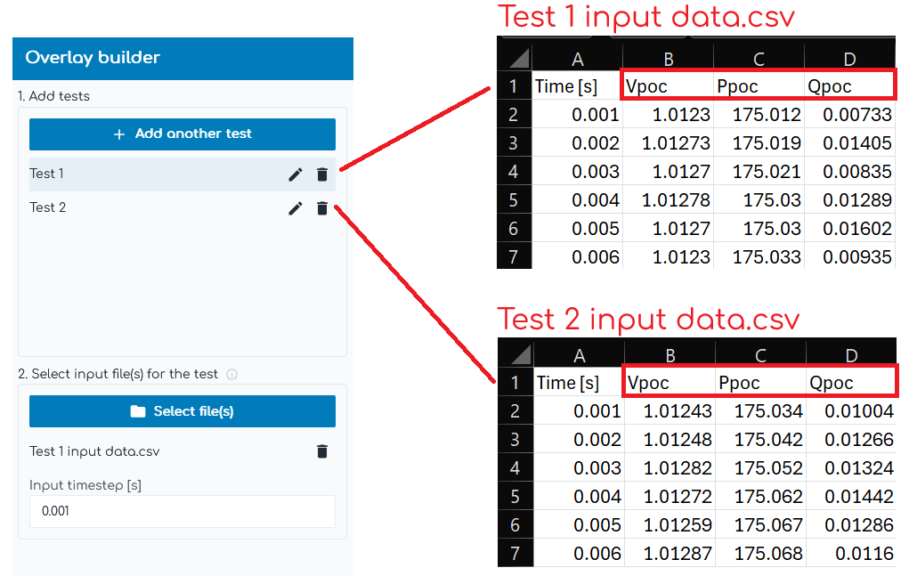
Checked: Input data files can have different column names representing the same output channel across tests. Output channel Commands are configured as Loop Variables, allowing the Commands to change between tests.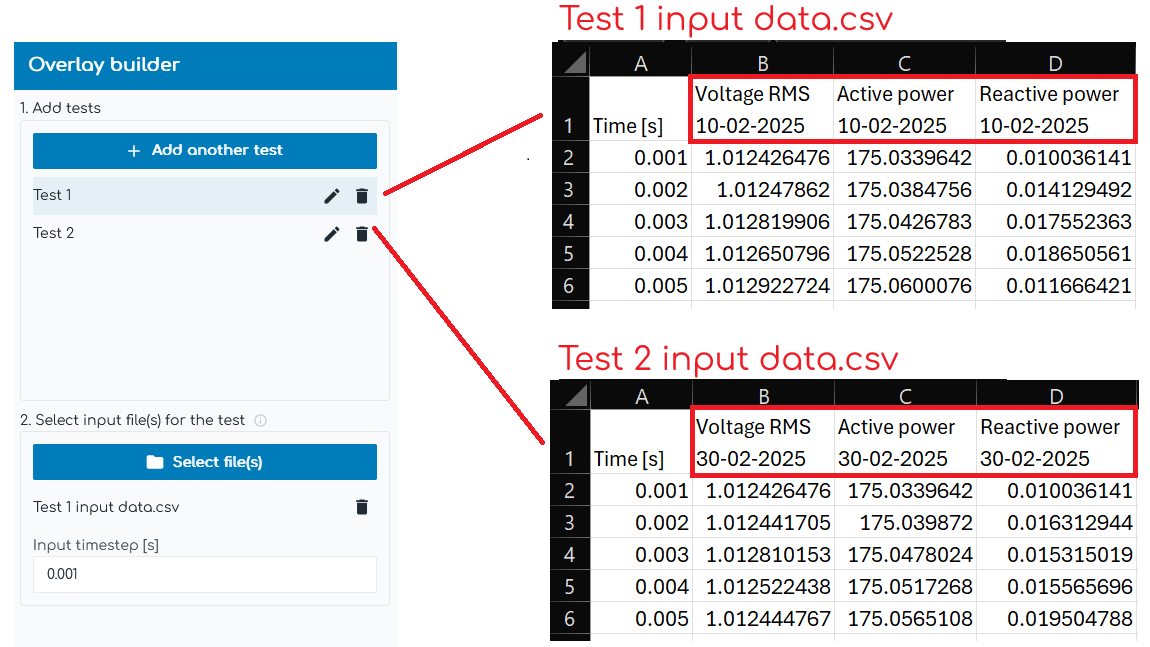
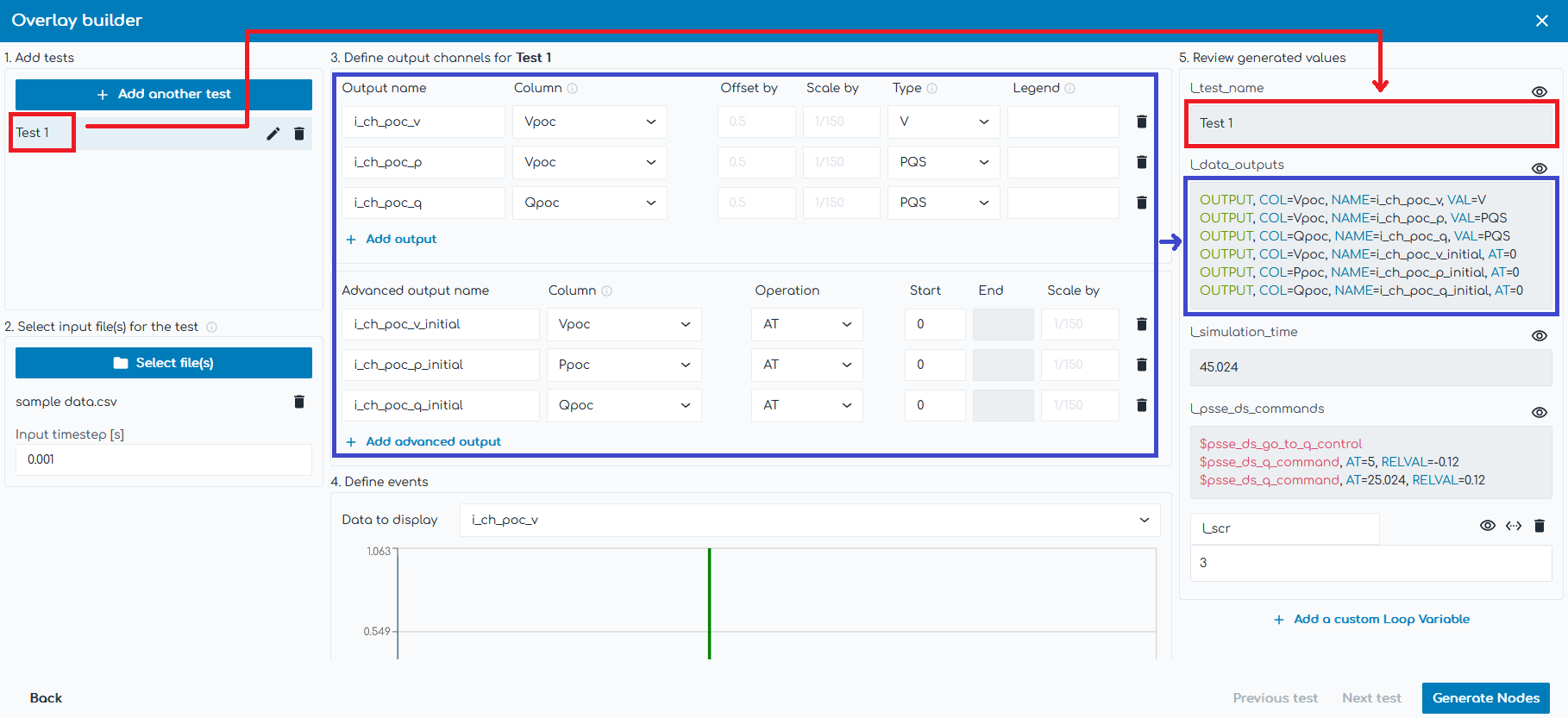
Test configuration space
1. Add tests
Add tests to the overlay builder. Each test becomes one loop in the configured Loop: Start Node.
2. Select input file(s) for the test
Select input file(s) for the relevant test and specify the associated time step of the data.
Files are used to help configure overlays, but are not uploaded to our servers or transferred to the simulation machine where your Engine is installed. Files must be located in the selected input folder which is accessible by your Engine.
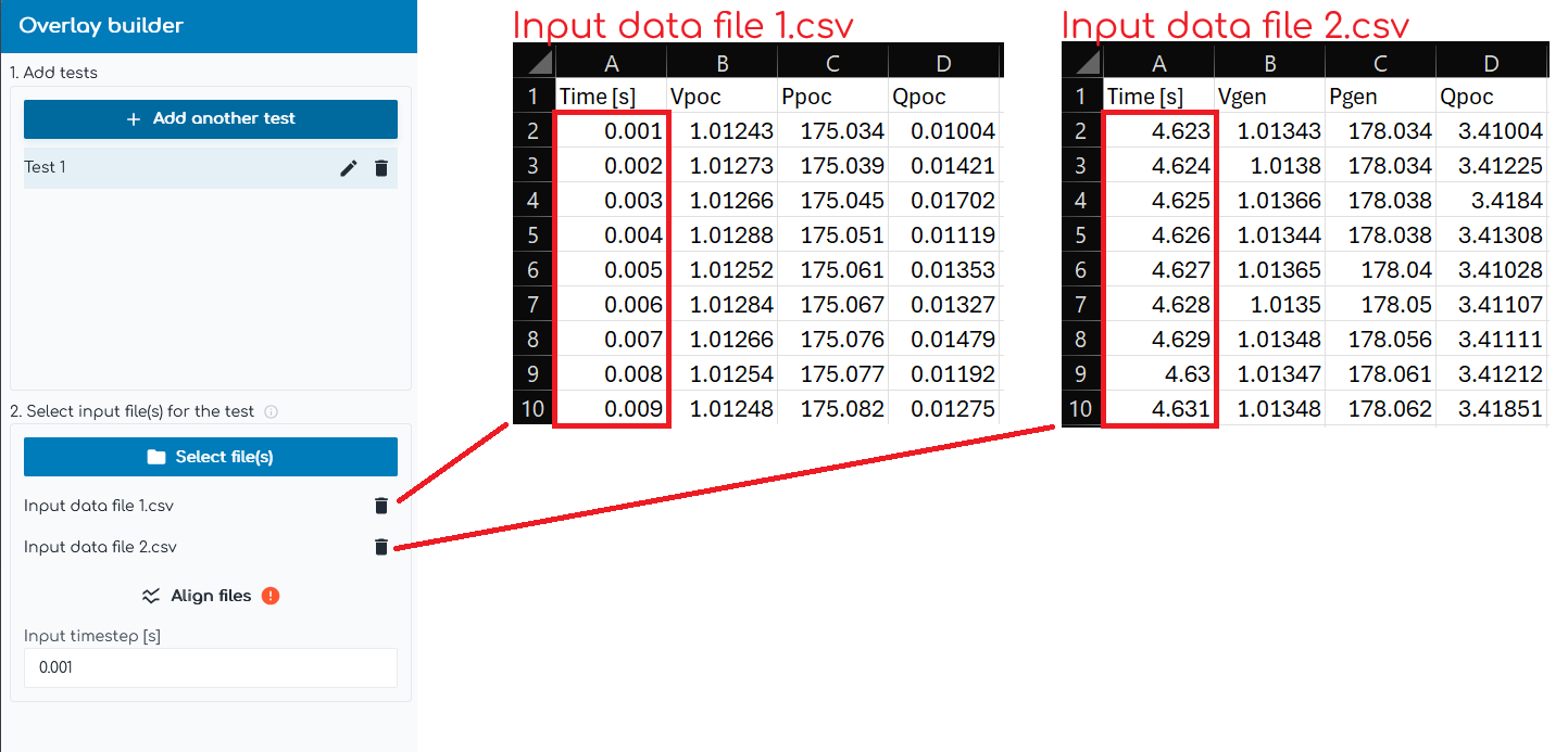
It is possible to select more than one file per test and x-axis align the input files such that columns from each file are accessible as if they were all in one file. If multiple files are selected, outputted columns must be unique across input files - irrespective of whether you enable "My tests have different column names" or not.
- Overlaying site data from one day with site data from another day. In this instance, you will be aligning events from different days.
- Overlaying site data with power systems software, where the site data is represented by multiple input files. For example, data from site may come from both a PPC meter and inverter terminal meter whose recordings were started at different times and have different time steps. As shown in the image below, the relative time of "0.001 [s]" in the first data file represents the same relative time as "4.623 [s]" in the second data file. The difference in time values is because the inverter terminal meter recording was started 4.622 seconds after the POC meter recording.
3. Define output channels
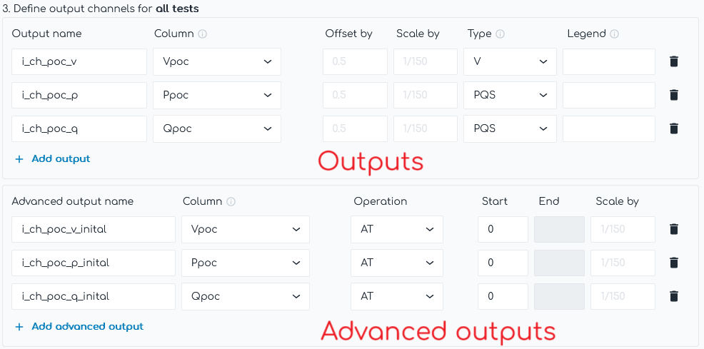
Define the output channels from the input data files. There are two types of output channels:
- Outputs: Outputs all the data from a particular column in the input data file as time-series data to be used later for plotting and/or further analysis.
- Advanced outputs: Outputs a single value based on advanced calculations on the data from a particular column in the input data file. This is typically used for selecting values to help initialize power system simulations.
- If "My tests have different column names" is disabled, the output channel definitions are the same across all tests.
- If "My tests have different column names" is enabled, the output channel definitions are configured individually for each test.
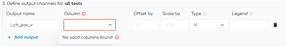
If no valid columns are found when defining output channels, it is most likely due to one of the following:
- "My tests have different column names" is disabled but the input data files have different column names representing the same output channel across tests. In this instance, enable "My tests have different column names".
- More than one file per test is selected but the columns are the same in each file. In this instance, please ensure that if multiple files are selected for a test, outputted columns are unique across input files.
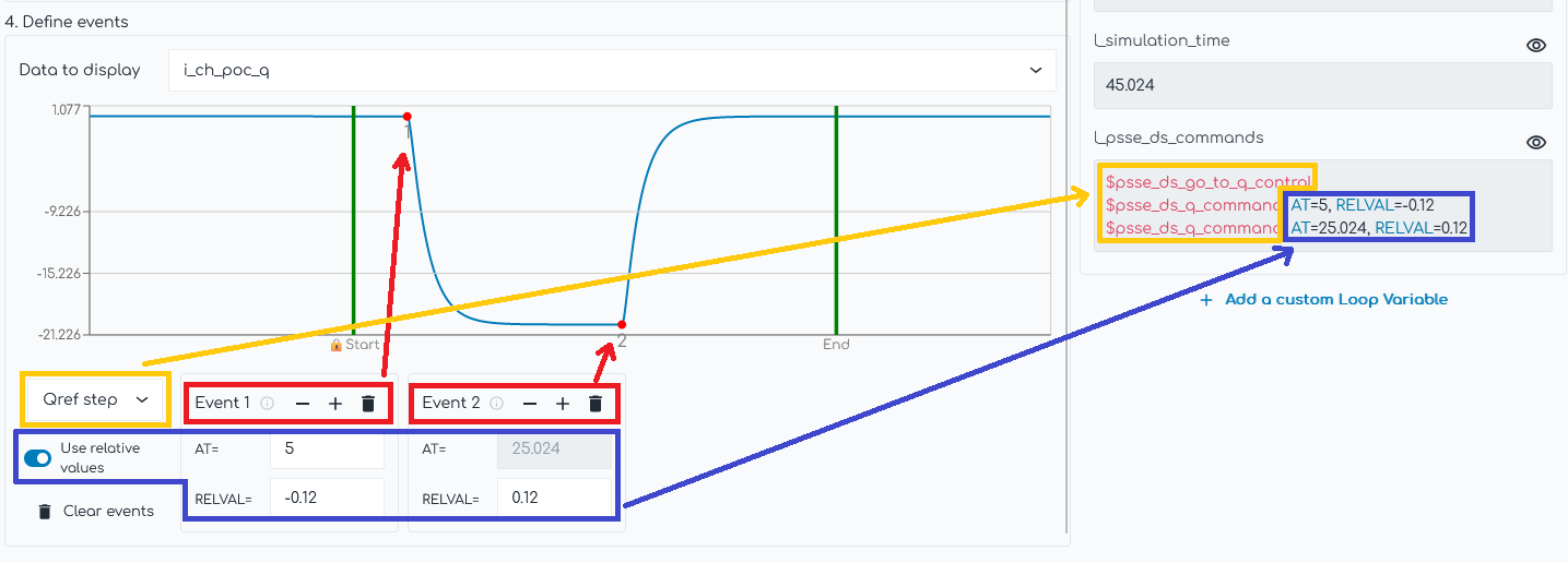
4. Define events
Define power system events which occurred in the input data. This is primarily used to help reproduce the tests in power systems modelling software ready for overlaying the results.
Configuring the type of test (e.g. Qref step), the time at which the event occurs (e.g. at 5 seconds) and the value/relative value change at each event (e.g. relative step of -0.12 p.u.) is enough information to generate Loop Variables specific to each power systems software (e.g. l_psse_ds_commands). These Loop Variables contain Commands which utilize existing Global Variables and can be used to reproduce the test from the input data.
You only need to configure the time at which the first event occurs (e.g. at 5 seconds). Once this first event time is configured, the time at which all other events occur can be calculated based on the number of rows in the input data separating the events as well as the time step [s].
5. Review generated values
As outlined above, the Overlay builder configures a Loop: Start Node and one or more Data Nodes based on input data files. This section allows you to review the generated values for some of the most important Loop Variables in the configured Loop: Start Node.
Additionally, you may create custom Loop Variables which will be inserted into the Loop: Start Node controlled by the overlay builder.
Using the generated Loop Variables
The Overlay builder configures a Loop: Start Node and one or more Data Nodes based on input data files. You can view all of the generated Loop Variables by opening the associated Loop: Start Node. Many of the generated Loop Variables are used directly inside the Data Node(s) (e.g. l_filename, l_manual_align_time and l_manual_align_index).
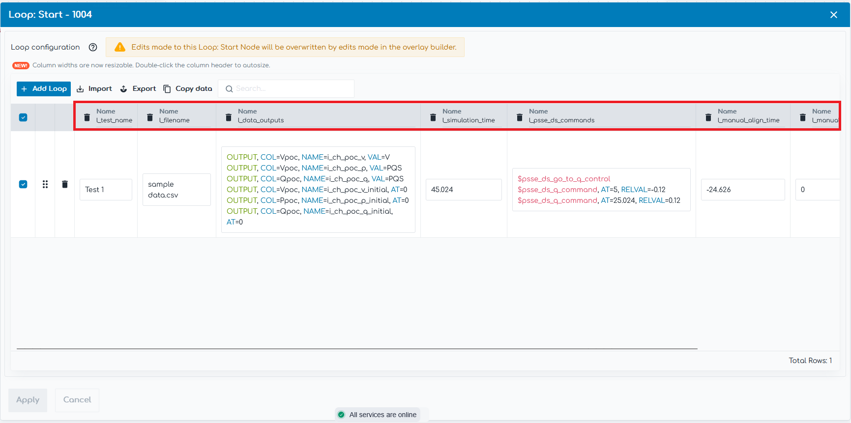
However, many of the generated Loop Variables are designed to be used in connected Nodes, such as:
- l_test_name: Test name is useful in Plot Nodes when configuring the subplot title.
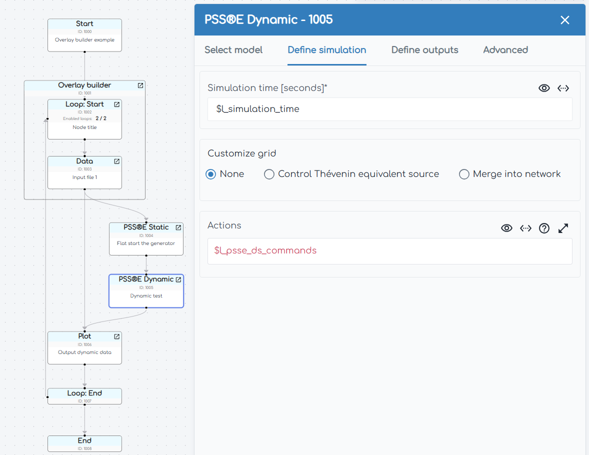
- l_simulation_time: Simulation time is useful in dynamic power system Nodes when configuring the simulation time as well as in Plot Nodes when configuring the x-axis: Max.
- l_psse_ds_commands (or similar): Generated power system specific dynamic Commands are designed to be inserted into the Actions field of the relevant dynamic power system Node.