Terms and definitions
There are several terms and definitions used throughout the gridmo software platform.
Engine
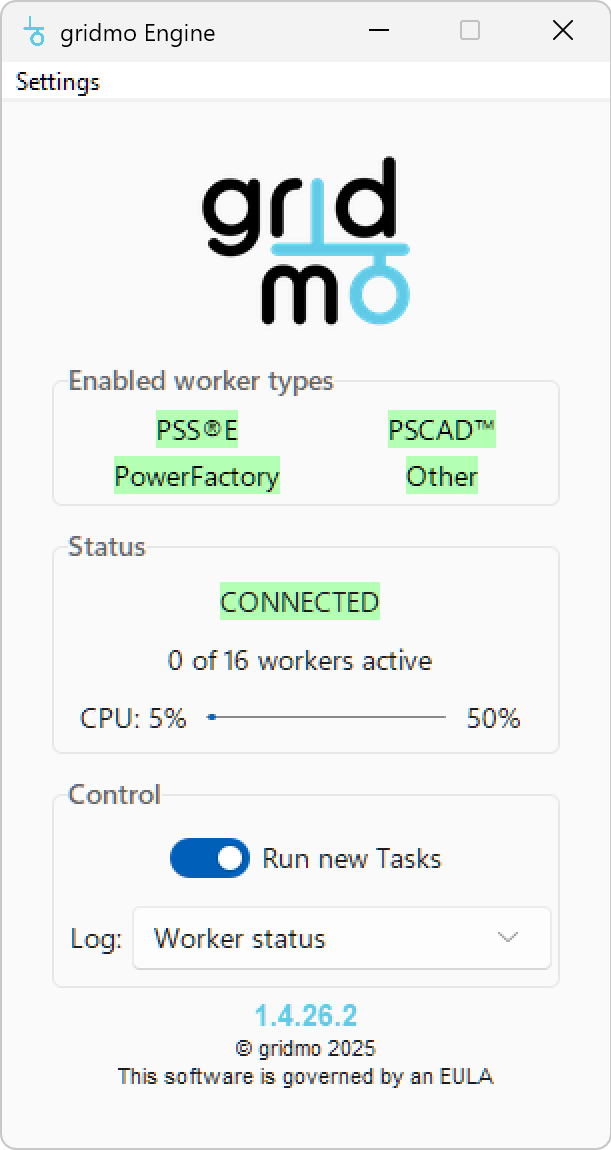
The gridmo Engine is a Windows OS executable which is used to locally run simulations. The Engine connects locally with your files and power systems software (e.g. PSS®E and PSCAD™). The Engine connects remotely with the gridmo web application to receive simulation instructions.
Nodes
Nodes are the fundamental building blocks of the web application. A Node represents one or more 'processing jobs' for the Engine. An example of a single Node is shown below.
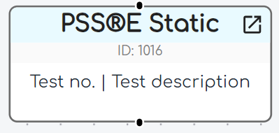
Some Nodes, such as PSS®E Static or PSCAD™, represent individual power system studies. Other Nodes, such as Plot or Table process results from other Nodes to generate outputs.
Edges
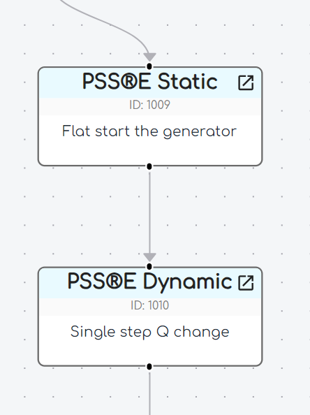
An Edge is a connection between any two Nodes. An Edge represents:
- The sequence in which Nodes should be processed; and
- The transfer of information between Nodes.
Edges are directional, as indicated by the arrow.
Runs
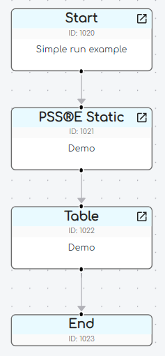
A Run represents a sequence of Nodes and Edges which:
- Starts at a
StartNode; and - Ends at an
EndNode.
Each Run:
- Is stand-alone, meaning a single Node or Edge can only belong to one Run; and
- May contain as many Nodes and Edges as required. We recommend each Run has one specific purpose, such as generating a single plot or sequence of plots.
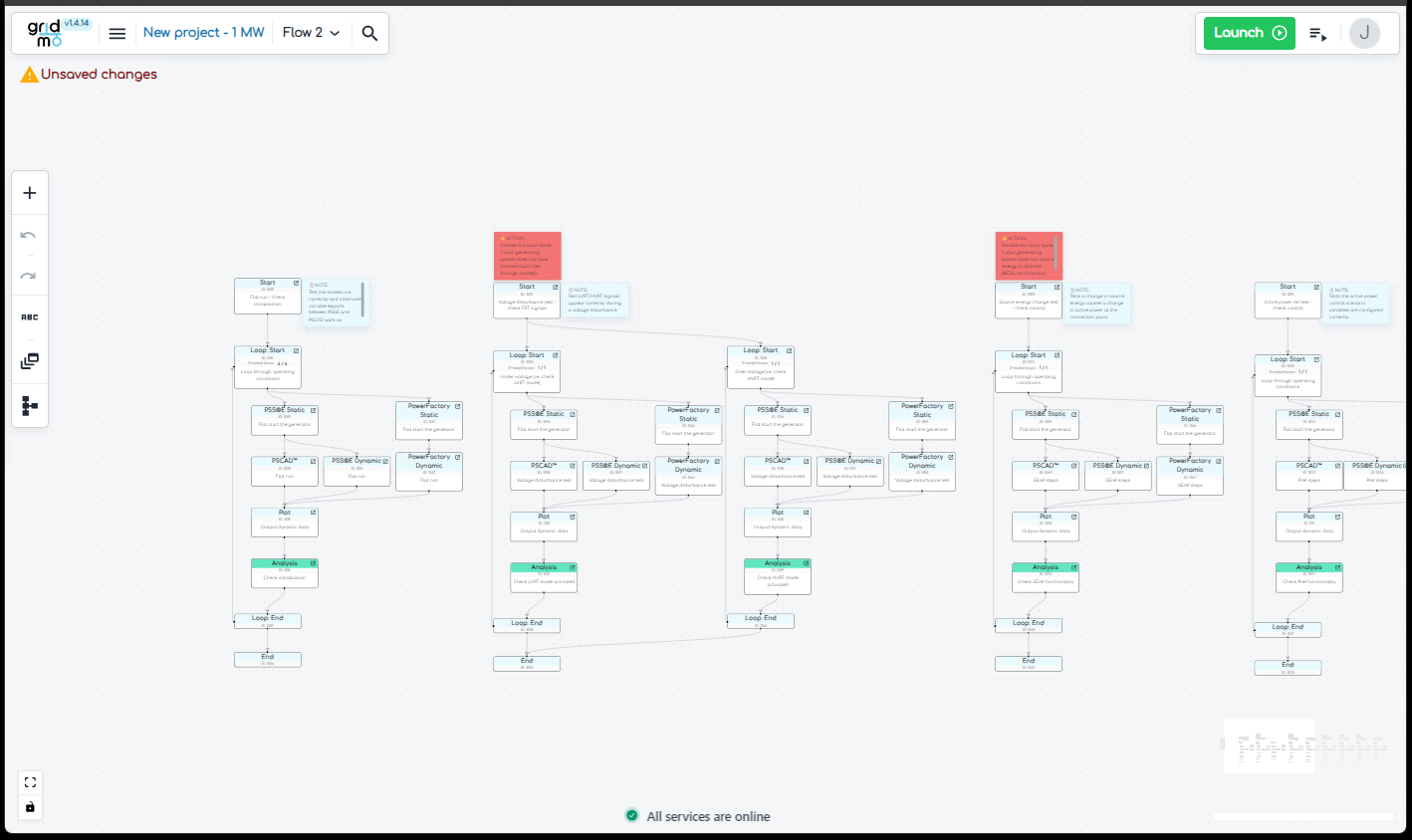
Flow
A Flow is a collection of one or more Runs.
Each Flow may contain as many Runs as required.
Project
A Project is made up of project settings and one or more Flows.
Variables
Variables are used to help define complex tests and to ensure tests from our Template Library work across different projects and OEMs.
Loop Variables
Loop Variables are entered in a Loop: Start Node and are used to repeat the Nodes between a Loop: Start and Loop: End Node pair, based on the number of Loop Variable values.
This functionality is used to help iterate over power system studies. To loop over a series of Nodes:
- Create a
Loop: StartNode - Connect an Edge from the bottom of the
Loop: StartNode to the first Node you want to loop over - Create a
Loop: EndNode - Connect the final Edge from the last Node you want to loop over to the top of the
Loop: EndNode - Connect the
Loop: StarttoLoop: EndNode using the left-most Edge handle - Configure the
Loop: StartNode with the Loop Variables
The example below shows a Run before and after adding a loop.
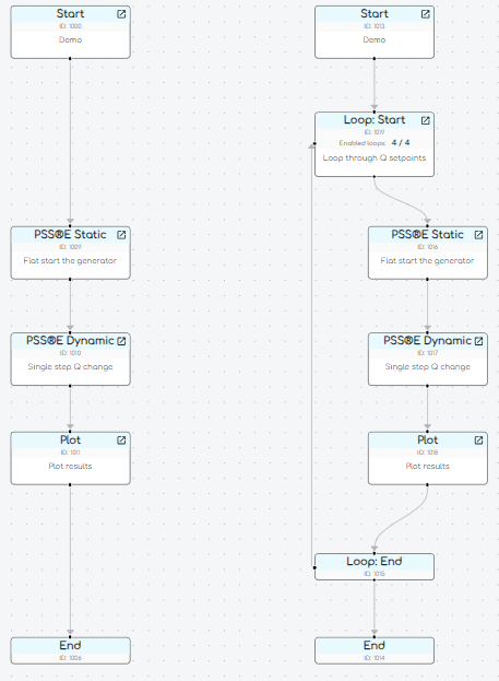
The $ symbol is used to identify the use of the variable - noting that Loop Variables only apply for Nodes between the relevant Loop: Start and Loop: End Nodes.
We recommend using l_ at the start of a Loop Variable name, with the name consisting of only lower case letters and underscores.
The following example loops over two variables, named 'l_scr' and 'l_xr'.
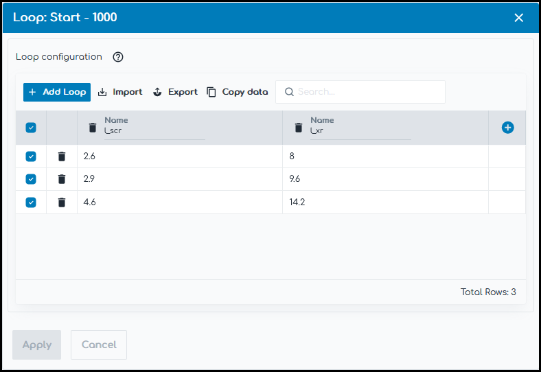
The above example will repeat the Nodes between the Loop: Start and Loop: End Nodes three times. Each time wherever $l_scr or $l_xr is found in the Node configuration, they are replaced with the Loop Variable values:
- First loop:
$l_scrwill be replaced with the value2.6and$l_xrwill be replaced with the value8. - Second loop:
$l_scrwill be replaced with the value2.9and$l_xrwill be replaced with the value9.6. - Third loop:
$l_scrwill be replaced with the value4.6and$l_xrwill be replaced with the value14.2.
Nested loops are not currently supported.
Internode Variables
Internode Variables provide the ability to transfer data between two connected Nodes. Internode Variables are identified using two curly brackets, such as {{i_variable_name}}.
We recommend using i_ at the start of an Internode Variable name, with the name consisting of only lower case letters and underscores.
Common Internode Variable use cases may include:
- Exporting a single value (e.g. generator terminal voltage) from a
PSS®E StaticNode to be used in aPSCAD™Node to assist with initialisation - Exporting an array of values (e.g. generator terminal active power) from a
PSS®E DynamicNode to aPlotNode to display the results in an output file
Internode Variables can be added to any input field within the Web App except for the following:
- Plot Node: Output file name field
- Table Node: File name field
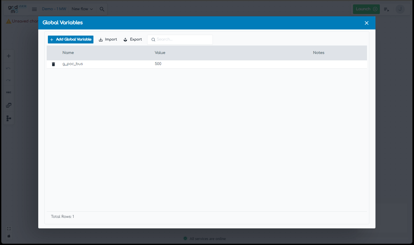
Global Variables
Global Variables are a convenient way of storing information which is used throughout the Project.
If a Global Variable is created named new_variable, with a value 3, anywhere that $new_variable is used throughout the Project, this will be replaced with the value 3.
To create a Global Variable:
- Navigate to the Global Variables window and click the
Add variablebutton. - Enter the variable name. Only letters, numbers and underscores are supported.
- Enter the variable value. Text including spaces is supported.
Alternatively, use the import/export functionality to complete bulk edits.
Common Global Variables for Projects may include:
- Project name
- Project revision, submission number and/or submission date
- File paths and names
Multiline partial commands
Multiline partial commands are a way of configuring reference change global variables to change multiple values in a model. This feature is often useful when a plant model has multiple power plant controllers (e.g. a large hybrid renewable generator system) or multiple terminal-level control generators (e.g. multiple terminal-control synchronous generating units).
You can enable multiline partial commands by clicking the three dots to the right of the variable and selecting 'Multiline partial command'.
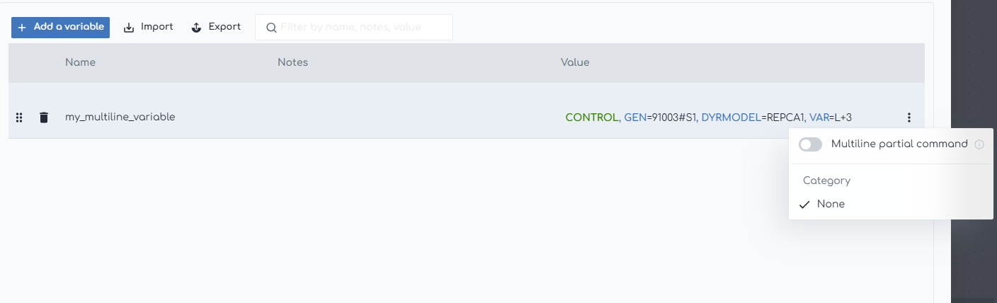
Once enabled, you can enter multiple lines of the variable value.
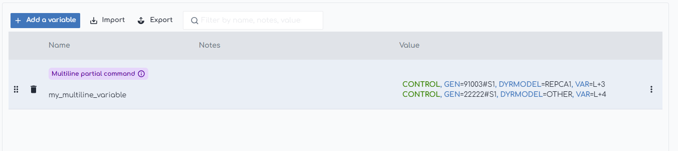
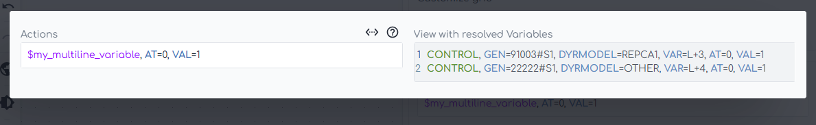
Then, when the variable is used, it will resolve as shown below:
Operating conditions Variables
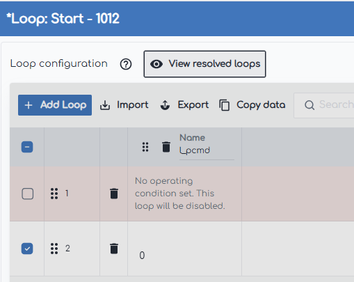
Operating conditions variables can only be used within the loops of a Loop: Start Node and are a way of increasing or decreasing the number of loops in a Run.
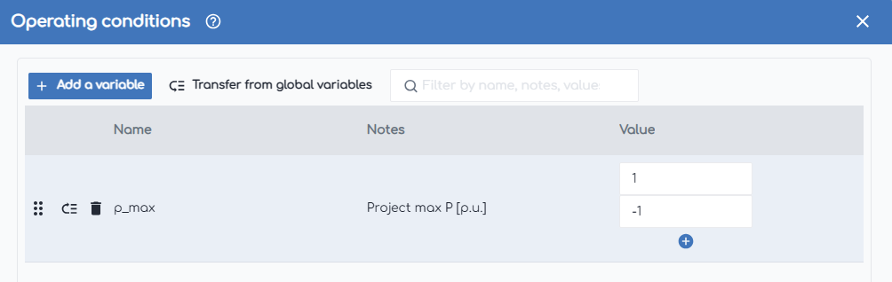
For example, you may have a Loop: Start Node with an l_pcmd loop variable, with values of $p_max and $p_min for each loop.
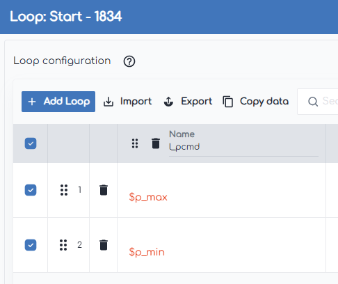
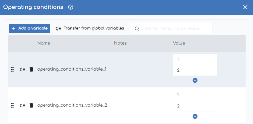
If you have multiple operating conditions with different values of $p_max, you can instead create an operating conditions variable named $p_max with values of 1 and -1.
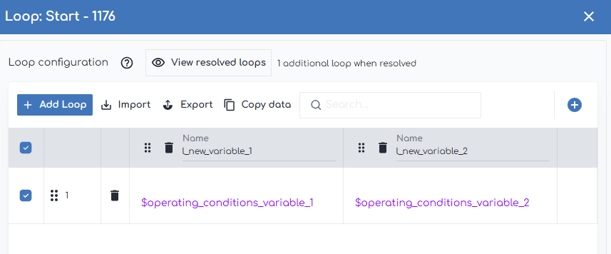
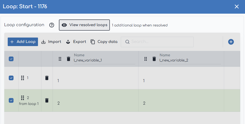
Now when you resolve the loops, you can see that an additional loop is created for each of the $p_max values.
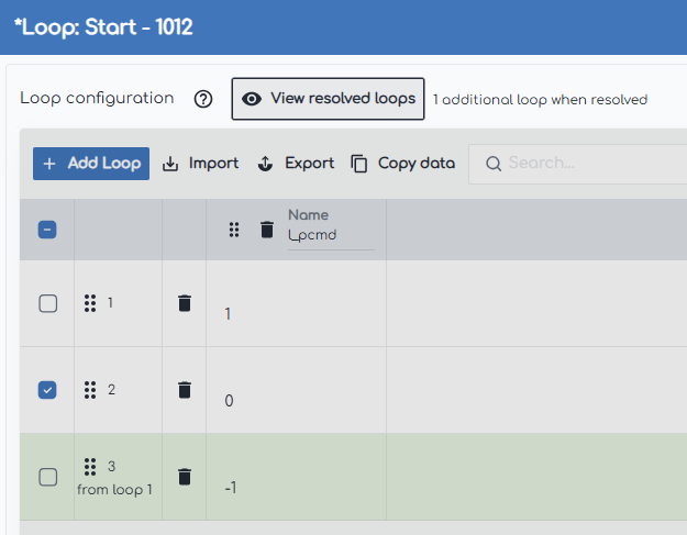
This is especially beneficial when you have a large number of Loop: Start Nodes across a project - you can now easily adjust the number of operating conditions without having to manually add or remove loops.
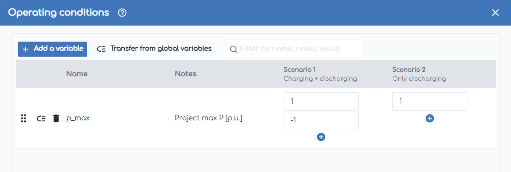
These variables also interact with scenarios. If scenarios are enabled, the operating conditions variables can have values specified for each scenario.
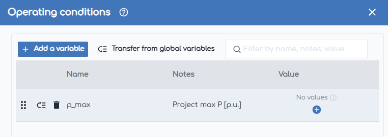
As well as being used to increase the number of loops, operating conditions variables can also be used to disable loops if they are not relevant. To do this, simply delete all values for that operating conditions variable.
If you want to use multiple operating conditions variables in the same loop, then they must have the same number of values for each scenario. When resolved, the operating conditions variables will resolve in sync to create the additional loops.
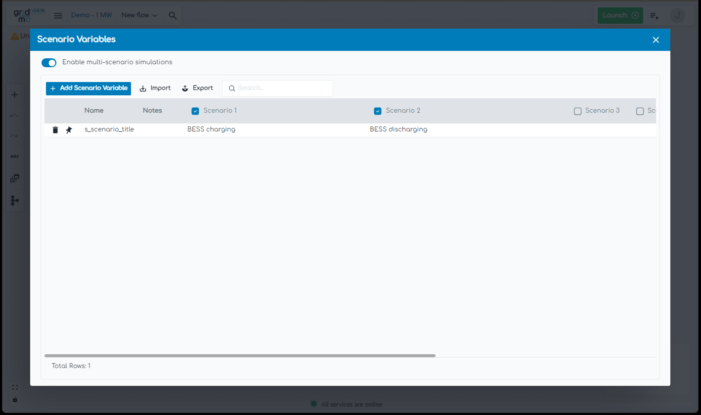
Scenario Variables
Scenario Variables allow the entire Flow to be run across multiple scenarios. Scenario Variables are typically used for hybrid generation plants where there are multiple scenarios (e.g. 'solar only', 'wind only', 'solar and wind').
If a Scenario Variable is created named scenario_description, with values of Solar only, Wind only and Solar and wind for scenarios S1, S2, and S3, the entire Flow will be run three times and anywhere that $scenario_description is used throughout the Flow, this will be replaced with the respective value.
To create a Scenario Variable:
- Navigate to the Scenario Variables window and click the
Add variablebutton. - Enter the variable name. Only letters, numbers and underscores are supported.
- Enter the variable value for each scenario. Text including spaces is supported.
- Enable/disable scenarios, as required.
Alternatively, use the import/export functionality to complete bulk edits.
Common Scenario Variables for Projects may include:
- Scenario name
- Commands which are relevant to specific scenarios
Tasks
Tasks are the individual 'processing jobs' being scheduled and run on the Engine. Each Node may be converted into zero or more Tasks depending on user configurations, such as whether loops are used or a run is enabled/disabled. This is primarily internal terminology, although users may see individual Task IDs when looking at the Engine worker status.
Commands
Commands allow users to configure tests. Commands are often specific to each Node type and have a combination of required and optional Arguments. There are Action Commands and Output Commands.
Actions
Actions are a type of Command which configure part of the test itself.
PSS®E Static | Example: Set bus 100 out of service.
SET, BUS=100, STATUS=OUT
Outputs
Outputs are a type of Command which configure the outputs of a test.
PSS®E Static | Example: Output the voltage [p.u.] at bus 100 and name the internode variable 'busvolts'.
OUTPUT, BUS=100, VAL=V, NAME=busvolts
Advanced Parameters
Advanced Parameters allow users to configure test details which are not commonly used. Advanced Parameters are often specific to each Node type.
PSS®E Dynamic | Example Advanced Parameter: Measure system angle relative to the generator which was the slack bus prior to starting the dynamic simulation.
sim.relative.angles=Yes
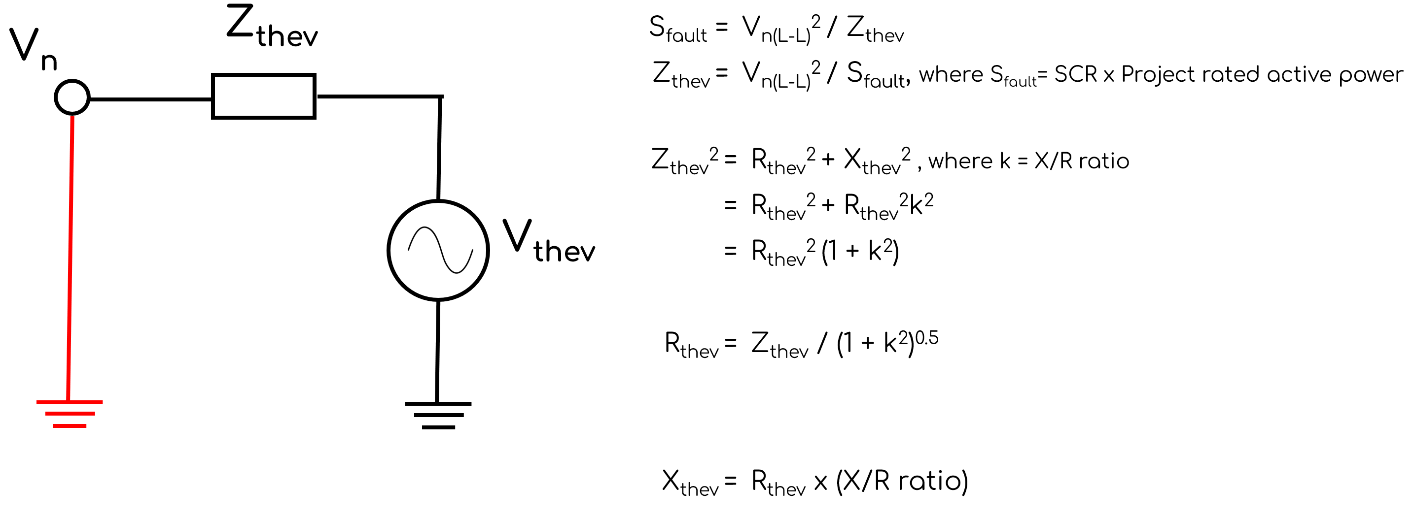
Thevenin equivalent impedance
Short circuit ratio
SCR (Short Circuit Ratio) is a standardised measure of system strength at a generator's connection point. There are multiple definitions, but gridmo has standardised on the following definition: SCR [unitless] = Three-phase fault level at the connection point [MVA] / Project rated active power [MW].
Despite the mismatching units (i.e. MVA v.s. MW), it is typically used as a dimensionless quantity.
SCR indicates the network's sensitivity to changes in apparent power at the connection point. For example:
- Lower SCR values indicate the connection point voltage is more sensitive to changes in apparent power.
- Higher SCR values indicate the connection point voltage is less sensitive to changes in apparent power.
X/R ratio
X/R ratio (Reactance to Resistance ratio) is the ratio of reactance [ohms at nominal system frequency] to resistance [ohms] of the Thevenin equivalent impedance.
The X/R ratio indicates the network's sensitivity to changes in active power v.s. reactive power. For example:
- Lower X/R values indicate the connection point voltage is more sensitive to changes in active power. This is more typical in distribution networks.
- Higher X/R values indicate the connection point voltage is less sensitive to changes in active power. This is more typical in transmission networks.
Calculation methodology
Short Circuit Ratio (i.e. SCR) and Reactance/Resistance ratio (i.e. X/R ratio) are often used in combination to specify the Thevenin equivalent impedance in SMIB studies. The following methodology is used to set the impedance based on provided SCR and X/R values.
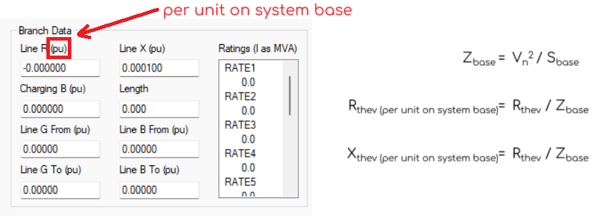
In PSS®E, branch values such as 'Line R (pu)' and 'Line X (pu)' are specified in per unit on system base, where system base is commonly set as 100 MVA. Therefore, the following additional calculations are required:
Infinite SCR
Infinite SCR is a fictitious network concept that implies no matter what apparent power is injected by the generating system, the point of connection voltage will not change. This concept is useful in some simulation studies. However, modelling infinite SCR is not always possible and is highly dependent on the particular power systems software - as infinite SCR implies an infinite fault level. Although some power systems software support zero impedance branches, we decided to avoid the use of zero impedance branches because they can increase simulation time (e.g. PSCAD™) or cause unintuitive behaviour where buses can be merged (e.g. PSS®E).
Engine before v1.5.0
Infinite SCR was defined as:
- SCR equal to the largest fault level each independent software could model. This methodology meant that they were the smallest impedance in each individual software, but depending on which software was being benchmarked this could cause small benchmarking misalignments.
- X/R ratio was not overridden, but defaulted to
1.0for many gridmo Templates, which could unintentionally create zero-impedance branches in some software packages.
Engine v1.5.0 and onwards
Infinite SCR is defined as:
SCR equal to the maximum fault level that can be modelled without creating zero impedance branches or causing numerical instability across all software packages that the gridmo Engine can automate. We calculate the largest fault level in each software according to the following logic:
- PSS®E: We assume the zero impedance line threshold value (i.e. THRSHZ) is set to the default of
0.0001p.u. on system base - a warning is raised if THRSHZ is not set to this value. We then read system base (e.g. 100 MVA). The maximum fault level without creating a zero impedance branch is then the system base divided by this impedance. - PSCAD™: Minimum series impedance of 0.0005 ohms × 2 (to avoid ideal branches under typical settings for PSCAD™).
- PowerFactory: PowerFactory's maximum fault level is much greater than that of PSS®E and is not currently a limiting factor in this calculation.
- DSATools™ PSAT & TSAT: We assume the zero impedance line threshold value (i.e. THRSHZ) is set to the default of
0.0001p.u. on a default100MVA system base. The maximum fault level without creating a zero impedance branch is then the system base divided by this impedance.
- PSS®E: We assume the zero impedance line threshold value (i.e. THRSHZ) is set to the default of
X/R ratio equal to infinite (i.e.
R=0) to avoid zero-impedance branches being created.
Power factor
Classically, power factor is defined as the ratio of real power to apparent power (e.g. P/S). However, this definition has several limitations and undefined behaviour. For example, the power factor is undefined when P=0 and Q=0.
To address these limitations, gridmo uses the following definition for power factor:

The sgn function is, in this context, the classical sign function modified such that it is never equal to 0.

This means that the power factor definition above adheres to generator convention, e.g. injecting reactive power is a positive power factor and absorbing reactive power is a negative power factor.
- Prior to gridmo Engine v1.11, the power factor was rounded to
1if the absolute value of the power factor was greater than0.9995503(which corresponds to an amount of reactive power within 3% of the active power value). - From gridmo Engine v1.11 onwards:
- This rounding has been effectively removed, with rounding to
1only applying for values extremely close to1(e.g. absolute value greater than0.999999). - This was implemented as visual anomalies were visible around power factor of
1on the new power factor subplot style.
- This rounding has been effectively removed, with rounding to
VAL_FUNCTION
VAL_FUNCTION is an argument supported in most commands which can be used to apply a user defined function to input or output values.
This is particularly useful when the values are not in the desired units (e.g. voltage is expressed in Volts, not p.u.).
VAL_FUNCTION can be used in place of VALSCALE and VALOFFSET to perform more complex operations. It cannot be used in conjunction with VALSCALE and VALOFFSET.
Syntax
VAL_FUNCTION=FUNCTION(VAL)
All functions must be written in the above format, where the FUNCTION is an arbitrary mathematical function operating on the input value VAL.
VAL will be replaced with the input value when the function is applied.
VAL should exist in every definition of VAL_FUNCTION, even if the function is being applied to different arguments (e.g. VAL/RELVAL/QMAX/etc.).
Supported functions
All functions listed in Math operations are supported with VAL_FUNCTION.
Supported notation
| Description | Examples |
|---|---|
| Brackets | (VAL + 1) / 2 |
Multiple instances of VAL | VAL**2 + 2*VAL + 1 |
| Nested functions | sin(acos(VAL)) |
Example 1 - Simple scaling of units
Scaling Pref from per unit on machine base to per unit on project rated active power.
CONTROL, GEN=91003#S1, DYRMODEL=REPCA1, VAR=L+3, VAL_FUNCTION=(175/200)*VAL, AT=5, VAL=1.0
Example 2 - Complex transformation of units
The unit of power factor in the OEM model is tan(θ). gridmo templates by default assume cos(theta). Therefore, transform PFref from tan(θ) to cos(theta).
CONTROL, GEN=91003#S1, DYRMODEL=REPCA1, VAR=L+99, VAL_FUNCTION=tan(acos(VAL)), AT=5, VAL=-0.98
Industry terms and definitions
| Term | Definition |
|---|---|
| DMAT | Dynamic Model Acceptance Test [AEMO] |
| Dynamic study | A study which emulates the real performance of network elements in a power system, conducted at a predefined time step. |
| GPS | Generator Performance Standards [AEMO] |
| Static study | A study which calculates the voltage, angle, active power and reactive power of network elements in a power system at a given moment. |