PowerFactory smiby

Last updated: 16 February 2026
Version: v1
Software required:
Background
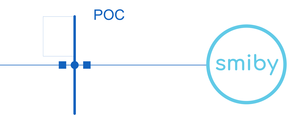
PowerFactory smiby provides a standardized Thévenin equivalent representation which helps you set up your PowerFactory model in gridmo. smiby is a PowerFactory Global template object (.IntTemplate) used to add a Thévenin equivalent representation into your SMIB model. The template is to be added to the point of connection of the generating system.
Although it is not required to use PowerFactory smiby (unlike PSCAD™ smiby for PSCAD™ simulations), it is recommended. The purpose of PowerFactory smiby is to eliminate any avoidable and time-consuming errors related to issues in your Thévenin equivalent representation (e.g. Thévenin source impedance abnormally high)
In gridmo, the Thévenin equivalent impedance is modelled in the branch ZTHEV rather than within the internal source impedance of the Thévenin equivalent generator. This design choice ensures that users have direct access to VTHEV. If the internal source impedance were set to a non-zero value, VTHEV would not be easily accessible. To avoid this limitation, gridmo represents ZTHEV externally, using an impedance branch connected to VTHEV.
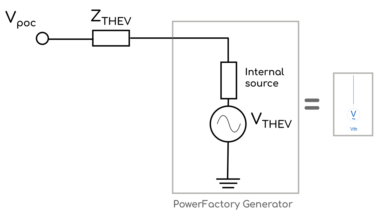
When using gridmo to set the site-specific SCR and X/R, the impedance of the branch ZTHEV will be adjusted accordingly.
Adding smiby into a model
Step 1: Remove existing Thévenin equivalent representation
Open the PowerFactory study case for your project and remove any existing external grid representation at the connection point. For example, to add PowerFactory smiby to the WECC solar case, first remove the existing Thévenin equivalent source representation so that the SMIB model terminates at the POC bus.
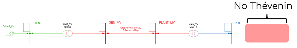
The existing Thévenin equivalent source representation in the PowerFactory WECC solar model is identical to PowerFactory smiby. This example is provided to demonstrate the process of adding the Thévenin equivalent source representation to your project model.
Step 2: Import PowerFactory smiby file into database
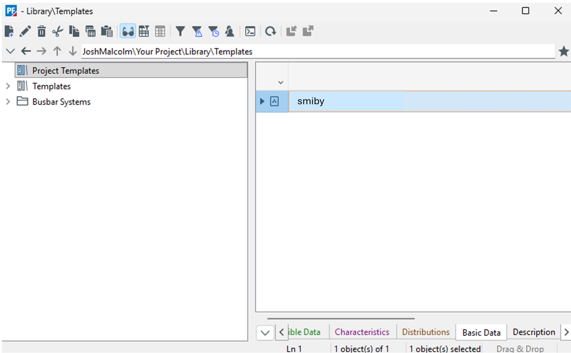
Import the PowerFactory smiby file smiby.pfd into your PowerFactory library.
The smiby.pfd is a PowerFactory template, by default it is imported alongside the project files in your PowerFactory database.
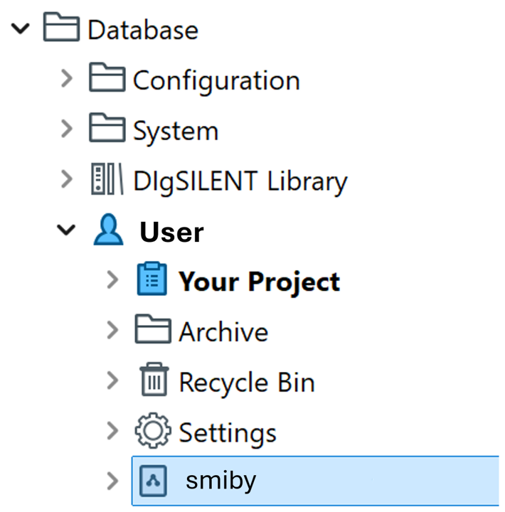
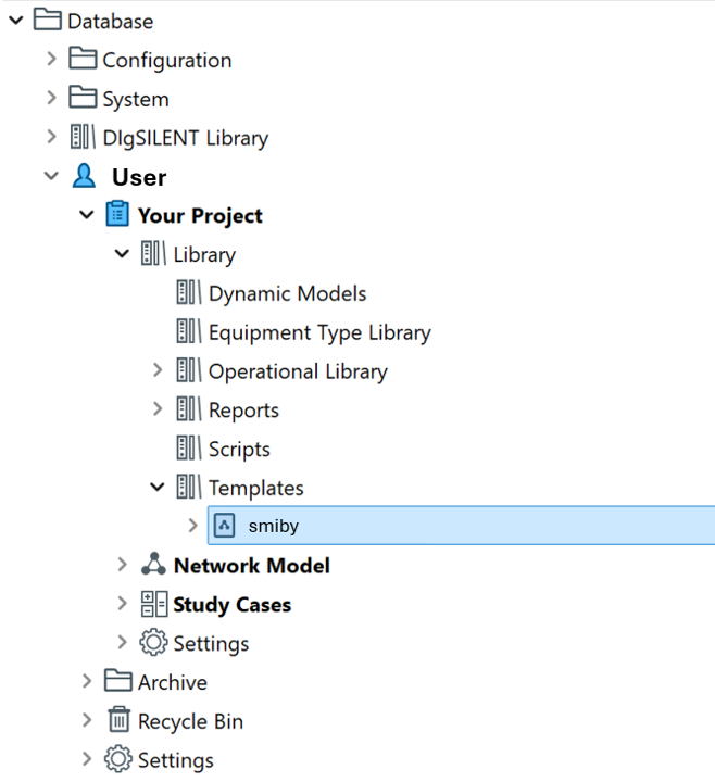
Your PowerFactory database should appear like this, with the smiby template as shown.
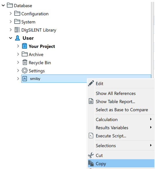
Step 3: Copy the PowerFactory smiby template file into your project
Now that the template file smiby is in your PowerFactory database, right click on the smiby template to copy.
Paste the smiby template object in the Templates folder of your project.
The Templates folder can be found within the Library folder of your project.
Step 4: Link the PowerFactory smiby template with your SMIB model
Activte your PowerFactory project. Unfreeze the diagram by selecting the lock symbol so that it switches to the unlocked state, allowing you to make changes to the diagram.

In the Drawing Tools pane, navigate to Templates -> General detailed templates. To do this, scroll down or use the search tab to look for templates. This is where the imported smiby template is stored. Select General detailed templates.

A window will appear. Click once on smiby once, now hover over your SMIB diagram and click where you want the smiby block to be placed.
Click once to preview, and then click again to place the block.
If it is placed close to the POC bus it will automatically connect. Otherwise, you can place the block at a location of your choice and manually connect it to the POC bus.

Once you have placed the smiby block, close the template window to avoid placing another smiby block. If you accidentally insert multiple instances of the smiby block, use Ctrl+Z to undo the extra instances.
Alternatively, go to the data manager and delete these objects from your project database:
Step 5: Check model
The smiby block should be successfully connected to your POC bus.
To view inside the smiby block, right click and select 'Show Detailed Diagram'
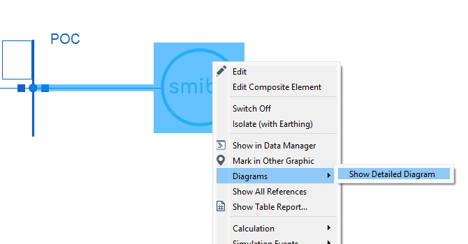
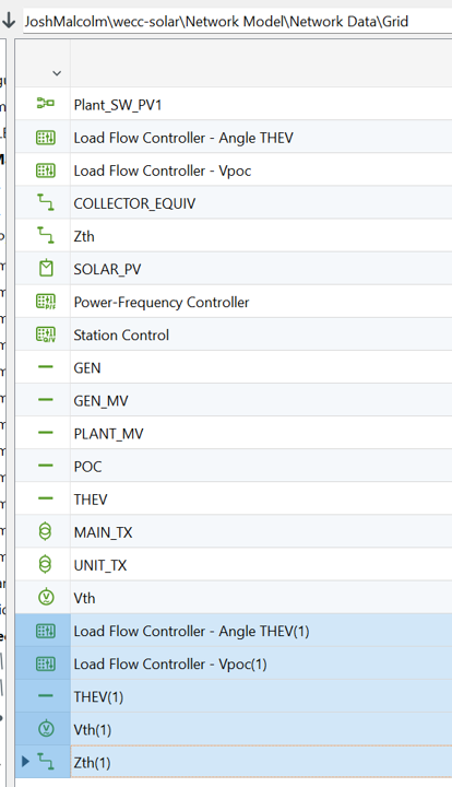
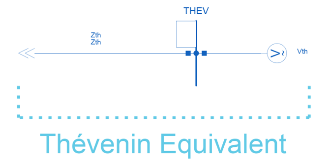
A separate diagram should open and show the following:
Step 6: Configure voltage and control
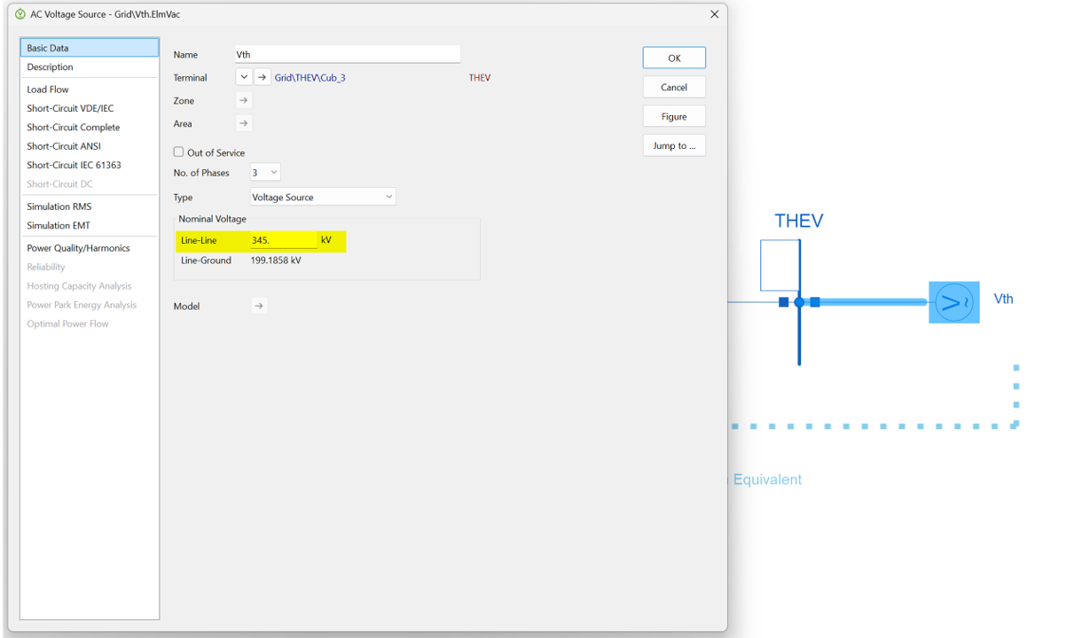
The next step is to configure the voltage of the Thévenin voltage source to match the nominal voltage of your point of connection. E.g. if your point of connection voltage is 345 kV, the Thévenin voltage source should also have a nominal voltage of 345 kV.
Update Vth
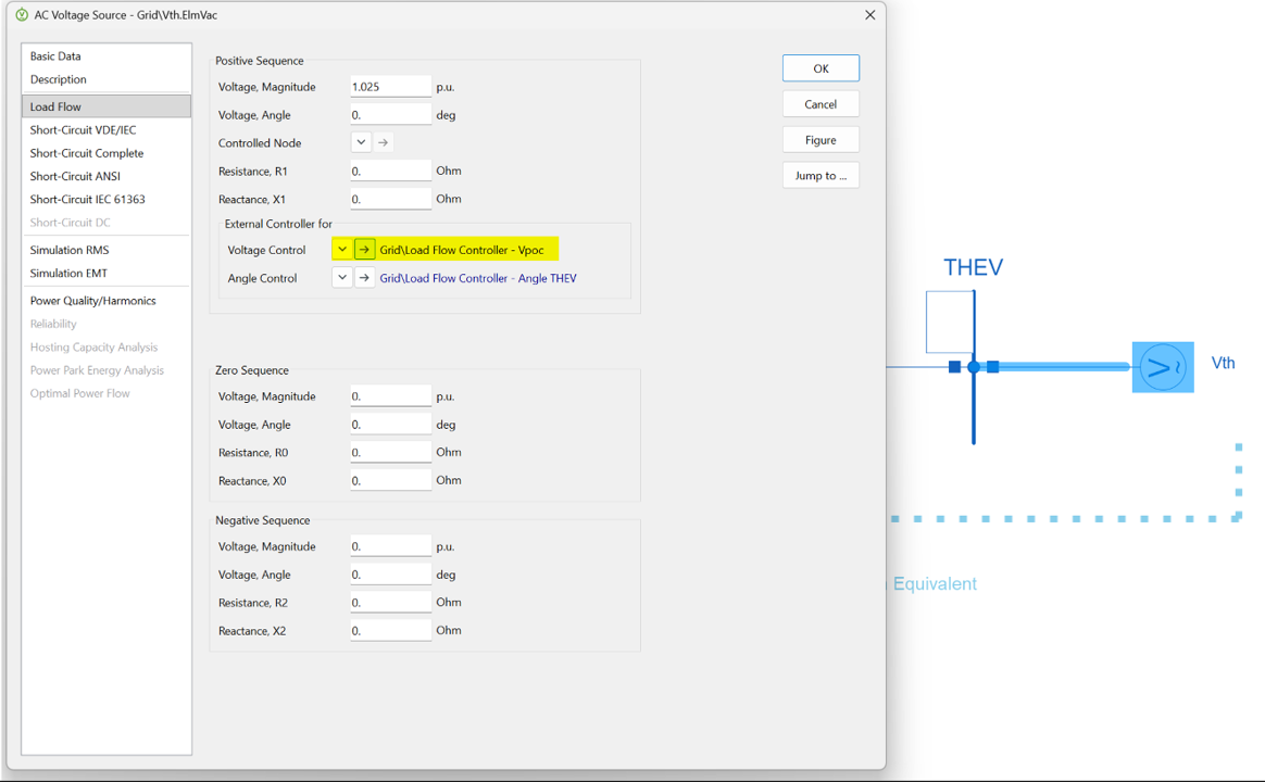
Update Load Flow Controller - Vpoc
The next step is to setup the Thévenin voltage control point. For this, navigate to the Load Flow section of the Thévenin voltage source. Select the external Voltage Control object Load Flow Controller - Vpoc as highlighted below.
A new window will appear. Navigate to the Load Flow section, then use the arrow to select the Bus Bar or Terminal where the voltage will be regulated. You should select the POC bus for your generating system.
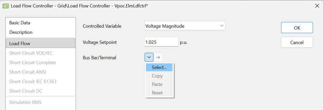
The voltage setpoint in the Load Flow Controller - Vpoc should be determining the voltage at your POC bus.
Update Load Flow Controller - Vpoc
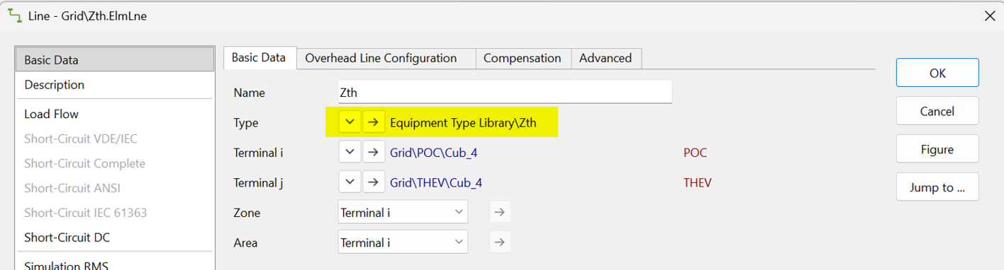
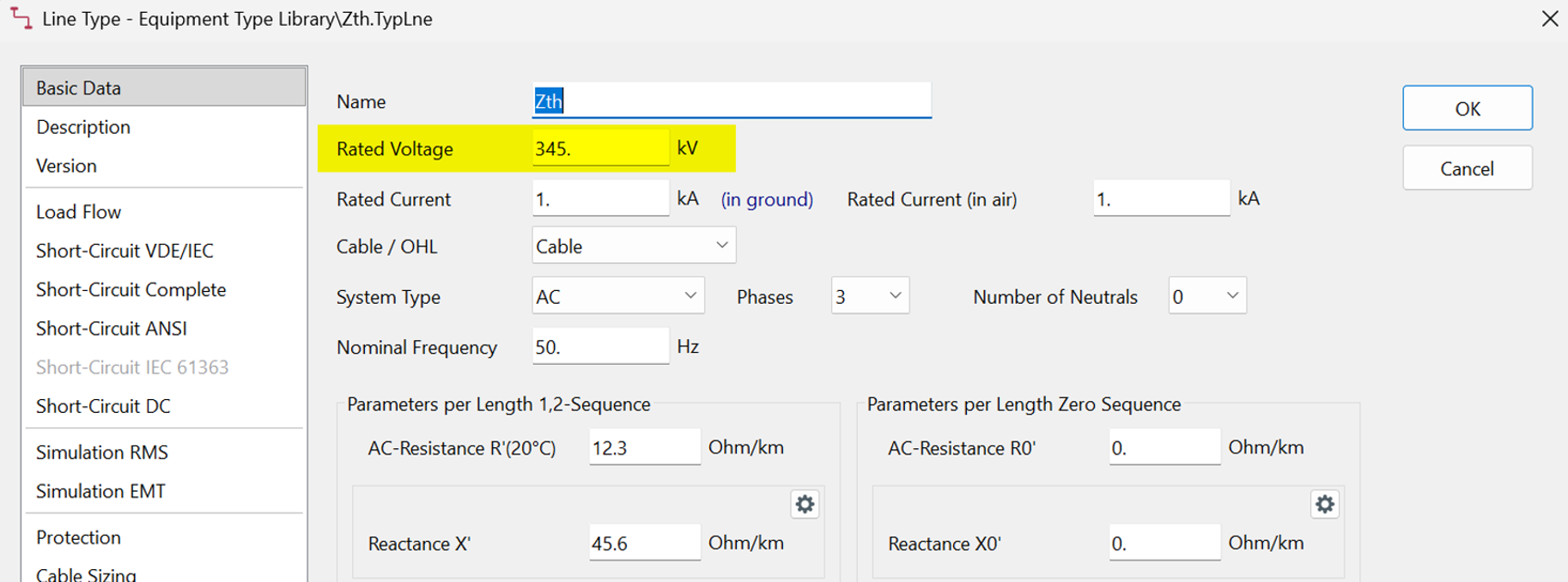
The rated voltage of the Zth line also needs to be set to the nominal voltage of your POC bus. This can be set by opening the Zth line element and selecting the line type and editing the rated voltage to match your POC nominal voltage.
It is recommended to run a load flow to check that the model is working as expected.
PowerFactory smiby is ready to go!
Step 7: (Optional) Ungroup smiby block
This step is optional and depends on your viewing preference.
The Graphical Freeze Mode needs to be turned off (Unfreeze) before completing this step.
The smiby block representation can remain as it is, or, if you prefer, the PowerFactory smiby block can be “ungrouped” so that the internal objects appear on the same page as the generating system rather than as a single consolidated block.
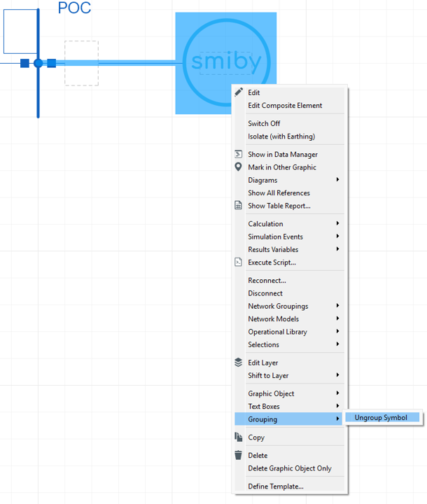
Once it is ungrouped it will look like the following:

All done, enjoy using PowerFactory smiby!
Revision history
Version 1 | 16 February 2026
- First release.