PSCAD™ termy

Last updated: 20 January 2026
Version: v3
Software required:
Background
termy is a PSCAD™ Definition provided with the gridmo software platform which enables gridmo to easily interface with your PSCAD™ Workspace. termy contains the metering components of the smiby block and is typically used for terminal-level metering.
Adding termy into a model
Step 1: Add termy to your PSCAD™ Workspace
Add the termy block into your PSCAD™ Workspace by the same process as adding the smiby block:
- Download the latest version of termy using the
DOWNLOAD MODELbutton above. - Open your PSCAD™ Workspace file from your gridmo Engine's Inputs folder (
.pswx) in PSCAD™. - Right click on the
Definitionsfolder underneath the PSCAD™ Case in the Workspace view and selectImport From File. - Navigate to the location of the termy definition file (
.psdx) and select it. - Right click on the
termydefinition (it will appear at the bottom of the list of definitions) and selectCopy. - Right click in the whitespace area in your Workspace, right click and select
Paste. - Move termy to the location you wish to meter, by inserting termy in between two PSCAD™ nodes.
You can have multiple termy blocks in your PSCAD™ Workspace to meter different locations.
Note that the smiby block has point of connection metering - therefore, typically, you don't need termy at your generating system's connection point.
Step 2: Configure termy parameters
To configure the termy block, right click on the termy block and navigate to 'Edit Parameters'. Update the 'Project settings' and 'FRT Flags' tabs as below:
Project settings
Name- This field can be used to distinguish between multiple termy blocks in a PSCAD™ workspace and when using the OUTPUT, LOCATION= Command. Set the
Namefield to a unique name such astermy_PVortermy_INV1.
- This field can be used to distinguish between multiple termy blocks in a PSCAD™ workspace and when using the OUTPUT, LOCATION= Command. Set the
The termy block has several parameters which define the base values of the internal metering. Set the following as per your project's base values:
Voltage base (kV)Frequency base (Hz)Project rated active power (MW)Active current id base (MW)Reactive current iq base (MVAr)
If your project's generating system is scaled within your model (i.e. number of inverters), you can scale the termy block's measurement outputs by using the Measurement scale field.
FRT flags
In the 'FRT flags' tab, link the FRT flags from your generating system with the termy block by configuring the following fields:
Single FRT flag or separate LVRT/HVRT flags?- If your generating system has a single flag for FRT select 'Single FRT flag', or 'Separate LVRT/HVRT flags' if you have individual flags for LVRT/HVRT.
FRT flag- If 'Single FRT flag' selected, enter the variable name of your FRT flag in this field.
LVRT flagandHVRT flag- If 'Separate LVRT/HVRT flags' selected, enter the variables names of your LVRT and HVRT flags here.
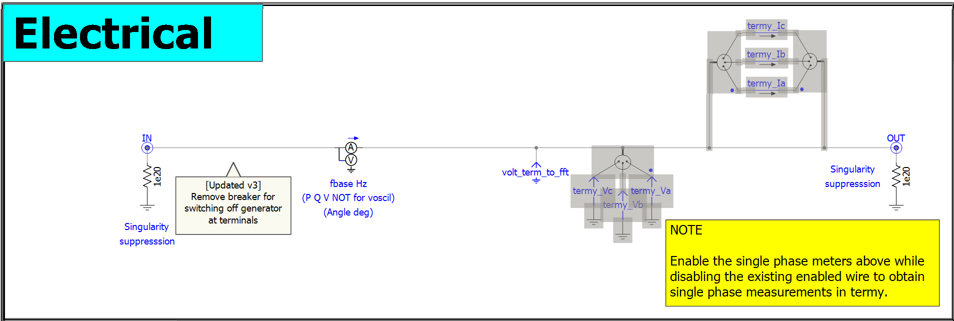
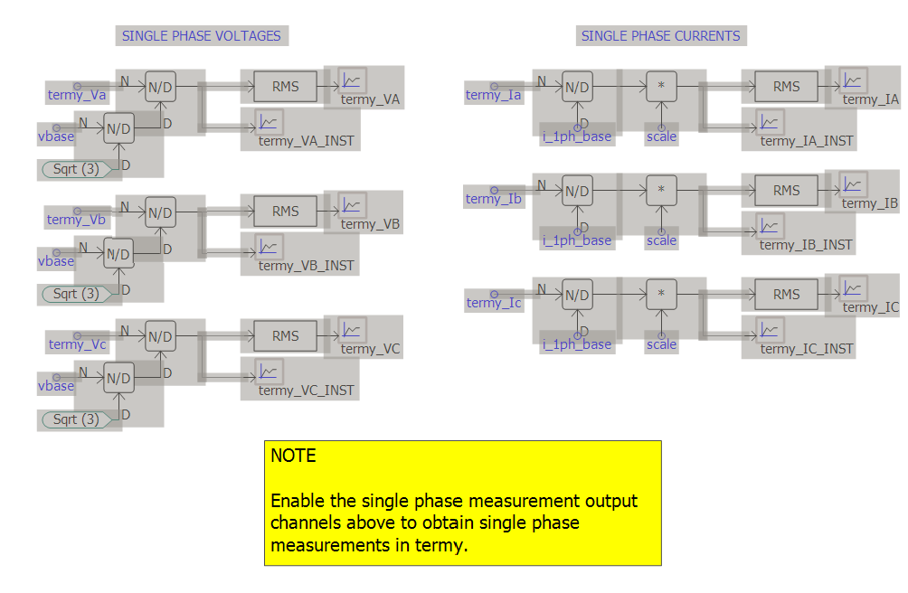
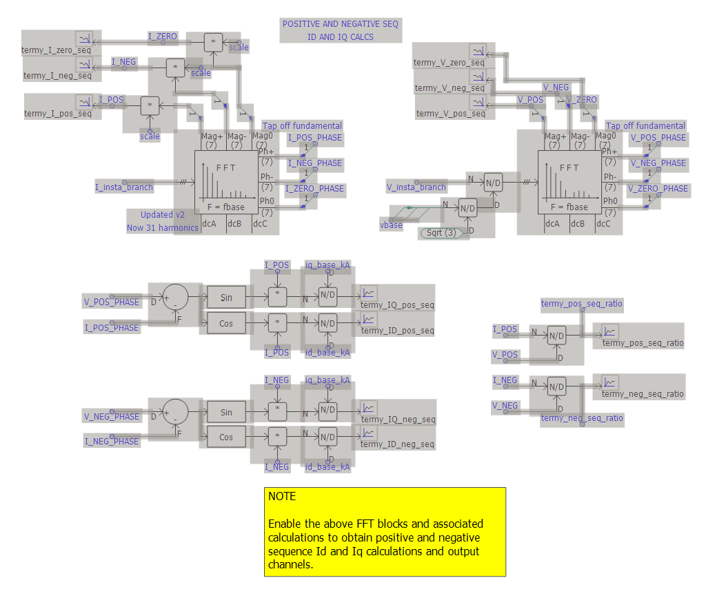
Step 3: Enable termy components for additional measurements (Optional)
termy's single phase metering and positive and negative sequence measurements are not enabled by default. If you require these, please enable the following components in the termy block:
Using termy's metering channels
The termy block has several built-in output channels which can be used. Replace LOCATION= with the name of the termy block you have set in the previous step.
The single phase measurements and positive, negative and zero sequence outputs below are not enabled by default inside the termy block. If required, please enable these inside termy (see Step 3 above) before using the output channels below.
Voltages
// Three phase RMS voltage [p.u. on base voltage configured in termy]
OUTPUT, LOCATION=<enter_termy_name_here>, TITLE=termy_VOLT, VAL=V, NAME=i_put_name_here
// Single phase RMS voltage [p.u. on base voltage configured in termy]
OUTPUT, LOCATION=<enter_termy_name_here>, TITLE=termy_VA, VAL=V, NAME=i_put_name_here
OUTPUT, LOCATION=<enter_termy_name_here>, TITLE=termy_VB, VAL=V, NAME=i_put_name_here
OUTPUT, LOCATION=<enter_termy_name_here>, TITLE=termy_VC, VAL=V, NAME=i_put_name_here

// Single phase instantaneous voltage [p.u. on base voltage configured in termy]
OUTPUT, LOCATION=<enter_termy_name_here>, TITLE=termy_VA_INST, VAL=V, NAME=i_put_name_here
OUTPUT, LOCATION=<enter_termy_name_here>, TITLE=termy_VB_INST, VAL=V, NAME=i_put_name_here
OUTPUT, LOCATION=<enter_termy_name_here>, TITLE=termy_VC_INST, VAL=V, NAME=i_put_name_here

// Positive, negative and zero sequence voltage [p.u. on base voltage configured in termy]
OUTPUT, LOCATION=<enter_termy_name_here>, TITLE=termy_V_pos_seq, VAL=V, NAME=i_put_name_here
OUTPUT, LOCATION=<enter_termy_name_here>, TITLE=termy_V_neg_seq, VAL=V, NAME=i_put_name_here
OUTPUT, LOCATION=<enter_termy_name_here>, TITLE=termy_V_zero_seq, VAL=V, NAME=i_put_name_here
Currents
// Single phase RMS currents [p.u. on base current configured in termy]
OUTPUT, LOCATION=<enter_termy_name_here>, TITLE=termy_IA, VAL=I, NAME=i_put_name_here
OUTPUT, LOCATION=<enter_termy_name_here>, TITLE=termy_IB, VAL=I, NAME=i_put_name_here
OUTPUT, LOCATION=<enter_termy_name_here>, TITLE=termy_IC, VAL=I, NAME=i_put_name_here

// Single phase instantaneous current [p.u. on base current configured in termy]
OUTPUT, LOCATION=<enter_termy_name_here>, TITLE=termy_IA_INST, VAL=I, NAME=i_put_name_here
OUTPUT, LOCATION=<enter_termy_name_here>, TITLE=termy_IB_INST, VAL=I, NAME=i_put_name_here
OUTPUT, LOCATION=<enter_termy_name_here>, TITLE=termy_IC_INST, VAL=I, NAME=i_put_name_here

// Positive, negative and zero sequence current [p.u. on base current configured in termy]
OUTPUT, LOCATION=<enter_termy_name_here>, TITLE=termy_I_pos_seq, VAL=I, NAME=i_put_name_here
OUTPUT, LOCATION=<enter_termy_name_here>, TITLE=termy_I_neg_seq, VAL=I, NAME=i_put_name_here
OUTPUT, LOCATION=<enter_termy_name_here>, TITLE=termy_I_zero_seq, VAL=I, NAME=i_put_name_here
// Three phase RMS active current [p.u. on base current configured in termy]
OUTPUT, LOCATION=<enter_termy_name_here>, TITLE=termy_ID, VAL=I, NAME=i_put_name_here

// Positive sequence active current [p.u. on base current configured in termy]
OUTPUT, LOCATION=<enter_termy_name_here>, TITLE=termy_ID_pos_seq, VAL=I, NAME=i_put_name_here

// Negative sequence active current [p.u. on base current configured in termy]
OUTPUT, LOCATION=<enter_termy_name_here>, TITLE=termy_ID_neg_seq, VAL=I, NAME=i_put_name_here
// Three phase RMS reactive current [p.u. on base current configured in termy]
OUTPUT, LOCATION=<enter_termy_name_here>, TITLE=termy_IQ, VAL=I, NAME=i_put_name_here

// Positive sequence reactive current [p.u. on base current configured in termy]
OUTPUT, LOCATION=<enter_termy_name_here>, TITLE=termy_IQ_pos_seq, VAL=I, NAME=i_put_name_here

// Negative sequence reactive current [p.u. on base current configured in termy]
OUTPUT, LOCATION=<enter_termy_name_here>, TITLE=termy_IQ_neg_seq, VAL=I, NAME=i_put_name_here
Powers
// Active power [MW] and reactive power [MVAr]
OUTPUT, LOCATION=<enter_termy_name_here>, TITLE=termy_P, VAL=PQS, NAME=i_put_name_here
OUTPUT, LOCATION=<enter_termy_name_here>, TITLE=termy_Q, VAL=PQS, NAME=i_put_name_here

// Power factor [unitless]
OUTPUT, LOCATION=<enter_termy_name_here>, TITLE=termy_PF, VAL=PF, NAME=i_put_name_here
Click here for details on how gridmo calculates power factor.
Ratios
// Positive and negative sequence ratios (Ipos/Vpos and Ineg/Vneg)
OUTPUT, LOCATION=<enter_termy_name_here>, TITLE=termy_pos_seq_ratio, NAME=i_put_name_here
OUTPUT, LOCATION=<enter_termy_name_here>, TITLE=termy_neg_seq_ratio, NAME=i_put_name_here
Other
// Frequency [Hz]
OUTPUT, LOCATION=<enter_termy_name_here>, TITLE=termy_FREQ, VAL=F, NAME=i_put_name_here

// Connection point voltage angle [degrees]
OUTPUT, LOCATION=<enter_termy_name_here>, TITLE=termy_ANGLE, VAL=ANGLE, NAME=i_put_name_here

// FRT flags
OUTPUT, LOCATION=<enter_termy_name_here>, TITLE=termy_LVRT, VAL=BINARY, NAME=i_put_name_here
OUTPUT, LOCATION=<enter_termy_name_here>, TITLE=termy_HVRT, VAL=BINARY, NAME=i_put_name_here
Updating termy to a new version
Update the termy block to the newest version by the same process as updating the smiby block:
- Download the latest version of termy.
- In PSCAD, navigate to your project containing the termy block(s) using the left hand sidebar, and expand 'Definitions' using the '+' symbol. Ensure that your current definition of the termy block is named 'termy' and not 'termy_1' or otherwise.
- Right click on 'Definitions', click 'Import from File' and select the 'termy_pscadv5.psdx' file you just downloaded. The new termy definition should appear as 'termy_1' in the project definitions.
- Open the scripts tab of PSCAD by navigating to the 'View' tab, select 'Panes' and then 'Scripts'.
- In the Scripts tab, click 'New' and navigate to the directory where the new termy version was downloaded. Select and open the 'gridmo_update_termy.py' script.
- Click 'Run' to update the termy block to the new version. Note that the script will automatically transfer all your project settings from the existing termy block.
- To complete the update, delete the old termy definition and rename the new definition to 'termy'.
Updating termy may overwrite any of your custom modifications to termy. In general, we recommend not making any changes to the termy block or OEM libraries so that newer versions may be accommodated easily.
Revision history
Version 3 | 20 January 2026
Improvements- Decreased sampling rate of point of connection On-Line Frequency Scanner component from 31 harmonics to 7 harmonics for speed improvements, as 31 harmonics are only required in rare instances.
- Removed circuit breaker within termy for switching off generator at terminals for speed improvements, as this is an uncommon method of switching off generating assets.
- Disabled single phase metering and output channels by default for speed improvements, as they are rarely required/used.
- Disabled On-Line Frequency Scanner components by default for positive and negative sequence calculations for speed improvements, as they are rarely required/used.
- Removed 1 kHz metering of terminal voltage (as not typically required for any tests).
Version 2 | 2 July 2025
New- Added output channels for instantaneous single-phase voltage and currents.
- Increased sampling rate of point of connection FFT frequency measurement from 7 harmonics to 31, to increase sampling rate to prevent false positives for system collapse due to extreme aliasing caused by the low sampling rate.
- Fixed signal names for output channels of single-phase current for phase B and C, where previously all three phases were incorrectly showing phase A current only (i.e.
termy_Ia).
Version 1 | 12 June 2025
- First release.