PSCAD™ smiby

Last updated: 19 June 2026
Version: v26
Software required:
Background
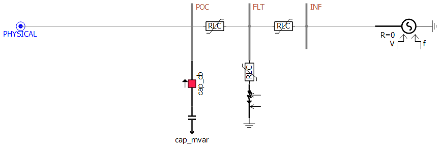
smiby is a PSCAD™ Definition provided with the gridmo software platform which enables gridmo to easily interface with your PSCAD™ Workspace. smiby is a Thévenin equivalent source, used for SMIB studies, which can be controlled using the Grid controls. A simplified representation of smiby is shown below.
Adding smiby into a model
The video below states that smiby can be found in your gridmo Engine's Inputs folder - this is no longer the case.
Instead - please download the latest version of smiby using the DOWNLOAD MODEL button above.
Step 1: Disable/remove existing external grid representation
Disable or remove the existing external grid representation (if any) at the connection point.
Step 2: Add smiby
Add the smiby block into your PSCAD™ Workspace. Add a single smiby block in the same PSCAD™ Case file (.pscx) where your existing external grid representation was disabled/removed. The three phase electrical grid connection is on the left hand side of smiby. In your PSCAD™ Case file, connect this to your connection point using the PSCAD™ wire tool. An example of a correctly configured PSCAD™ Case file is shown below.
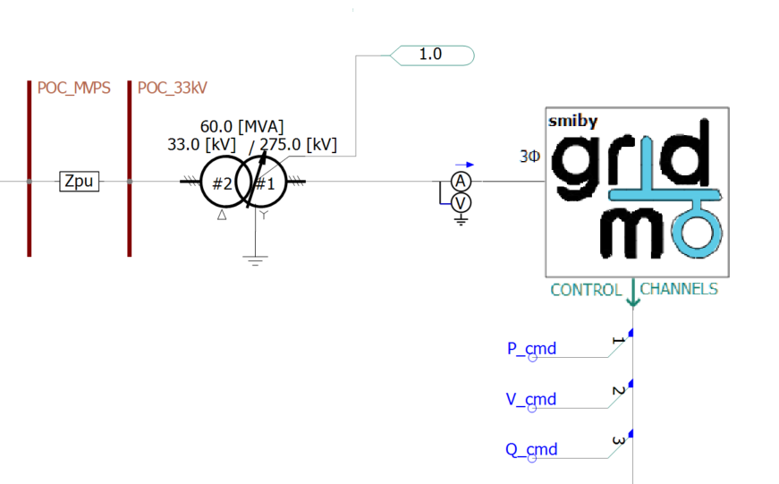
Step 3: Configure control channels
In addition to providing a controllable Thévenin equivalent source, smiby also contains independent multi-purpose control channels which can be controlled using the CONTROL Command. Control channels should normally be used for values which you may want to vary during a PSCAD™ simulation. Examples of common control channels:
- Active power reference
- Reactive power reference
- Voltage reference
- Power factor reference
- Source energy reference (e.g. wind speed, solar irradiance)
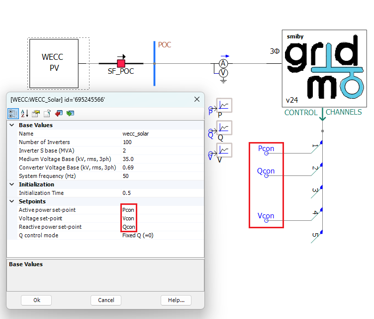
In your PSCAD™ Case file, connect these control channels to your generating system using the PSCAD™ wire tool and Data Signal Array Tap.
In the smiby parameter window, configure the following settings for each control channel:
- Enable/disable: This defines whether the control channel is enabled or disabled. You do not need to manually enable each channel, the gridmo Engine will automatically enable a channel when a matching
CONTROL, CH=Command is found in any given simulation. - Scale: This defines the scaling applied to any
CONTROLCommands (i.e. control channel output =CONTROLCommand value x scale). This scale is applied to the default value. - Defaults: This is the control channel output value used if there are no
CONTROLCommands for this channel.
Depending on the definition of a 3rd party or black-boxed PSCAD™ model, you can use the control channels as parameters by defining the channel with a name and adding the value into the parameters box.
Depending on the definition of a 3rd party or black-boxed PSCAD™ model, you may not be able to use the control channels as parameters by defining the channel with a name and adding the value into the parameters box (as shown above). In this instance, we strongly caution against using the Wireless Radio Link component to transfer the reference signals into the PSCAD™ model because this component can introduce time step delays which may cause model initialization issues.

Step 4: Configure smiby parameters
Right click on the smiby block and navigate to 'Edit Parameters'. In the 'Project settings' section, set the following values considering the requirements of your generating system:
- Voltage base (
float): Base line-to-line voltage at the connection point [kV]. - Frequency base (
float): Base frequency [Hz]. - Project rated active power (
float): The combined maximum amount of active power that the generating system is rated to deliver at the connection point. This value is used in combination with plant SCR commands. When run via gridmo Engine, this will be overwritten byProject settings:Project rated active power [MW]. - Active current id base (
float): Base active power used in Id calculation. This value is often set as the maximum amount of active power that the generating system is rated to deliver at the connection point [MW]. - Reactive current iq base (
float): Base active power used in Iq calculation. This value is often set as the maximum amount of apparent power that the generating system is rated to deliver at the connection point [MVAr]. - Current base [
float]: Current used for three phase RMS and single phase current base output channels [A].
In the 'Advanced' section of the smiby parameters, the apparent power base has been set to 100 MVA by default. Note that if you are benchmarking with PSS®E and your PSS®E model has a system base which is not 100 MVA, you must update this apparent power base in smiby to match with the system base used in PSS®E.
From smiby versions v20 and onwards, the circuit breaker at the POC can be controlled (i.e. for asset switch-off tests) using the following commands:
// If smiby v25 or newer, use the following command:
CONTROL_CB_POC, AT=<enter desired time>, STATUS=OUT  // Open circuit breaker (take generator out of service)
CONTROL_CB_POC, AT=<enter desired time>, STATUS=IN  // Close circuit breaker (put generator in service)

// Legacy commands (which override the CONTROL_CB_POC command) for smiby v22+:
SET, CNAME=smiby, PARAM=open_poc_cb, VAL=0 // Close circuit breaker (put generator in service)
SET, CNAME=smiby, PARAM=open_poc_cb, VAL=1 // Open circuit breaker (take generator out of service)

// Legacy commands (which override the CONTROL_CB_POC command) for smiby v20+:
SET, CNAME=POC_BUS_OFF, PARAM=Value, VAL=0 // Close circuit breaker (put generator in service)
SET, CNAME=POC_BUS_OFF, PARAM=Value, VAL=1 // Open circuit breaker (take generator out of service)
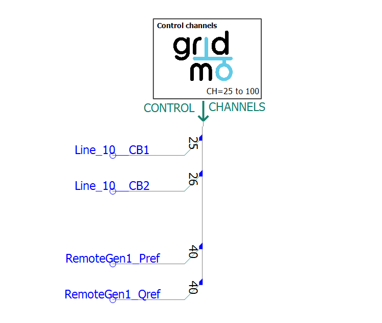
Independent control channels block
The independent control channel block provides an additional 76 control channels (from channel 25 to channel 100). It is designed to be used:
- When controlling very large plant (multiple PPC and/or multiple connection point); or
- When controlling multiple generators and/or status of lines/equipment e.g. (Australian REZ models or wide-area models).
The independent control channel block does not require smiby to be present, so it can be used for models which don't require Thévenin source representation such as wide-area PSCAD™ model simulations.
The definition for this block is available in the same .zip file as the main smiby definition.
To add this block to your PSCAD™ model:
- Follow the YouTube video above, except select the
gridmo_independent_channels.psdxdefinition instead of thesmiby_pscadv5.psdxfile. - Configure the default value and scale for the channels you want to use based on Step 3 above
The gridmo Engine will automatically enable a channel if a matching CONTROL, CH= Command is found.
You do not need to enable each channel (on the Enable/disable tab) you intend to use inside the independent channels block.
Using smiby's metering channels
The smiby block has several built-in output channels which can be used:
Voltages
// Three phase RMS voltage [p.u. on base voltage configured in smiby] at the connection point
OUTPUT, TITLE=smiby_POC_VOLT, VAL=V, NAME=i_put_name_here

// Three phase RMS voltage [p.u. on base voltage configured in smiby] at the infinite bus
OUTPUT, TITLE=smiby_INF_VOLT, VAL=V, NAME=i_put_name_here
// Single phase RMS voltage [p.u. on base voltage configured in smiby] at the connection point
OUTPUT, TITLE=smiby_POC_VA, VAL=V, NAME=i_put_name_here
OUTPUT, TITLE=smiby_POC_VB, VAL=V, NAME=i_put_name_here
OUTPUT, TITLE=smiby_POC_VC, VAL=V, NAME=i_put_name_here

// Positive, negative and zero sequence voltage [p.u. on base voltage configured in smiby] at the connection point
OUTPUT, TITLE=smiby_POC_V_pos_seq, VAL=V, NAME=i_put_name_here
OUTPUT, TITLE=smiby_POC_V_neg_seq, VAL=V, NAME=i_put_name_here
OUTPUT, TITLE=smiby_POC_V_zero_seq, VAL=V, NAME=i_put_name_here
Currents
// Three phase RMS current [p.u. on base current configured in smiby] at the connection point
OUTPUT, TITLE=smiby_POC_I, VAL=I, NAME=i_put_name_here
// Single phase RMS current [p.u. on base current configured in smiby] at the connection point
OUTPUT, TITLE=smiby_POC_IA, VAL=I, NAME=i_put_name_here
OUTPUT, TITLE=smiby_POC_IB, VAL=I, NAME=i_put_name_here
OUTPUT, TITLE=smiby_POC_IC, VAL=I, NAME=i_put_name_here

// Positive, negative and zero sequence current [p.u. on base current configured in smiby] at the connection point
OUTPUT, TITLE=smiby_POC_I_pos_seq, VAL=I, NAME=i_put_name_here
OUTPUT, TITLE=smiby_POC_I_neg_seq, VAL=I, NAME=i_put_name_here
OUTPUT, TITLE=smiby_POC_I_zero_seq, VAL=I, NAME=i_put_name_here
// Three phase RMS active current [p.u. on base current configured in smiby] at the connection point
OUTPUT, TITLE=smiby_POC_ID, VAL=I, NAME=i_put_name_here

// Positive sequence active current [p.u. on base current configured in smiby] at the connection point
OUTPUT, TITLE=smiby_POC_ID_pos_seq, VAL=I, NAME=i_put_name_here

// Negative sequence active current [p.u. on base current configured in smiby] at the connection point
OUTPUT, TITLE=smiby_POC_ID_neg_seq, VAL=I, NAME=i_put_name_here
// Three phase RMS reactive current [p.u. on base current configured in smiby] at the connection point
OUTPUT, TITLE=smiby_POC_IQ, VAL=I, NAME=i_put_name_here

// Positive sequence reactive current [p.u. on base current configured in smiby] at the connection point
OUTPUT, TITLE=smiby_POC_IQ_pos_seq, VAL=I, NAME=i_put_name_here

// Negative sequence reactive current [p.u. on base current configured in smiby] at the connection point
OUTPUT, TITLE=smiby_POC_IQ_neg_seq, VAL=I, NAME=i_put_name_here
Powers
// Active power [MW] and reactive power [MVAr] at the connection point
OUTPUT, TITLE=smiby_POC_P, VAL=PQS, NAME=i_put_name_here
OUTPUT, TITLE=smiby_POC_Q, VAL=PQS, NAME=i_put_name_here

// Power factor [generator convention] at the connection point
OUTPUT, TITLE=smiby_POC_PF, VAL=PF, NAME=i_put_name_here
Click here for details on how gridmo calculates power factor.
Channel readback
// Read back from smiby's output channels (e.g. to validate that the output channels are working)
OUTPUT, TITLE=smiby_CH1, NAME=i_put_name_here
OUTPUT, TITLE=smiby_CH2, NAME=i_put_name_here
OUTPUT, TITLE=smiby_CH3, NAME=i_put_name_here
OUTPUT, TITLE=smiby_CH4, NAME=i_put_name_here
OUTPUT, TITLE=smiby_CH5, NAME=i_put_name_here
OUTPUT, TITLE=smiby_CH6, NAME=i_put_name_here
OUTPUT, TITLE=smiby_CH7, NAME=i_put_name_here
OUTPUT, TITLE=smiby_CH8, NAME=i_put_name_here
OUTPUT, TITLE=smiby_CH9, NAME=i_put_name_here
OUTPUT, TITLE=smiby_CH10, NAME=i_put_name_here
OUTPUT, TITLE=smiby_CH11, NAME=i_put_name_here
OUTPUT, TITLE=smiby_CH12, NAME=i_put_name_here
// smiby v25 onwards:
OUTPUT, TITLE=smiby_CH13, NAME=i_put_name_here
OUTPUT, TITLE=smiby_CH14, NAME=i_put_name_here
OUTPUT, TITLE=smiby_CH15, NAME=i_put_name_here
OUTPUT, TITLE=smiby_CH16, NAME=i_put_name_here
OUTPUT, TITLE=smiby_CH17, NAME=i_put_name_here
OUTPUT, TITLE=smiby_CH18, NAME=i_put_name_here
OUTPUT, TITLE=smiby_CH19, NAME=i_put_name_here
OUTPUT, TITLE=smiby_CH20, NAME=i_put_name_here
OUTPUT, TITLE=smiby_CH21, NAME=i_put_name_here
OUTPUT, TITLE=smiby_CH22, NAME=i_put_name_here
OUTPUT, TITLE=smiby_CH23, NAME=i_put_name_here
OUTPUT, TITLE=smiby_CH24, NAME=i_put_name_here
Channel readbacks are not available for channels 25-100 included in the independent control channel block.
Ratios
// Short circuit ratio [Sfault / Pmax]
OUTPUT, TITLE=smiby_POC_SCR, NAME=i_put_name_here

// Thévenin source reactance to resistance X/R ratio [X/R]
OUTPUT, TITLE=smiby_POC_XR, NAME=i_put_name_here
// Positive sequence ratio (Ipos/Vpos) at the connection point
OUTPUT, TITLE=smiby_POC_pos_seq_ratio, NAME=i_put_name_here

// Negative sequence ratio (Ineg/Vneg) at the connection point
OUTPUT, TITLE=smiby_POC_neg_seq_ratio, NAME=i_put_name_here
Other
// Connection point frequency [Hz]
OUTPUT, TITLE=smiby_POC_FREQ, VAL=F, NAME=i_put_name_here

// Connection point voltage angle [degrees]
OUTPUT, TITLE=smiby_POC_ANGLE, VAL=ANGLE, NAME=i_put_name_here

// Thévenin source angle [degrees] (smiby v25 onwards)
OUTPUT, TITLE=smiby_INF_ANGLE, VAL=ANGLE, NAME=i_put_name_here

// Angle between voltage and reactive power [degrees] at the connection point
OUTPUT, TITLE=smiby_POC_VQ_phase, NAME=i_put_name_here

// Angle between frequency and active power [degrees] at the connection point (smiby v25 onwards)
OUTPUT, TITLE=smiby_POC_FP_phase, NAME=i_put_name_here

// |Z| and X/R ratio of applied fault (SIMPLEFAULT or VDISTURBANCE) (smiby v25 onwards)
OUTPUT, TITLE=smiby_FAULT_XR, NAME=i_put_name_here
OUTPUT, TITLE=smiby_FAULT_Z, NAME=i_put_name_here
Over-voltage snubber circuit
In versions of smiby earlier than v18, the following optional mode was called 'pre-insertion resistors' and worked in a similar way, however the resistance target was not dependent on the SCR and X/R ratio.
The VDISTURBANCE command controls the smiby block to apply a disturbance to the connection point. Under-voltages are applied via a fault block in PSCAD™, whereas over-voltages are applied by switching in/out an ideal capacitor. A capacitive load block in PSCAD™ is not suitable as it cannot be changed at runtime, meaning it limits to a single over-voltage event per simulation.
As PSCAD™ is an EMT tool, switching in an ideal capacitor can cause substantial oscillation of the RMS voltage at the connection point, especially under low SCR conditions.
To mitigate this, a non-linear snubber circuit is activated by default in the smiby block to dampen the oscillations caused by the ideal capacitor. The snubber circuit is a resistor connected in series with the capacitor. The resistor's resistance starts at the critical damping value (given the SCR and X/R) and decays rapidly after switched in. The snubber circuit is only active when a capacitor is switched in for an over-voltage disturbance.
However, due to the non-linear nature of the snubber circuit, there may be a damped initial rise time which is longer than the result from RMS tools. The rise time may be up to 75 ms at very high SCR values or for severe overvoltages.
The snubber circuit is enabled by default, however, to disable the snubber circuit, set the Use snubber circuit to dampen oscillations? to No in the VDISTURBANCE section of smiby, or alternatively use the following gridmo command in your PSCAD™ node.
SET, CNAME=smiby, PARAM=cap_capcharge2_enabled, VAL=0 // turn off snubber circuit
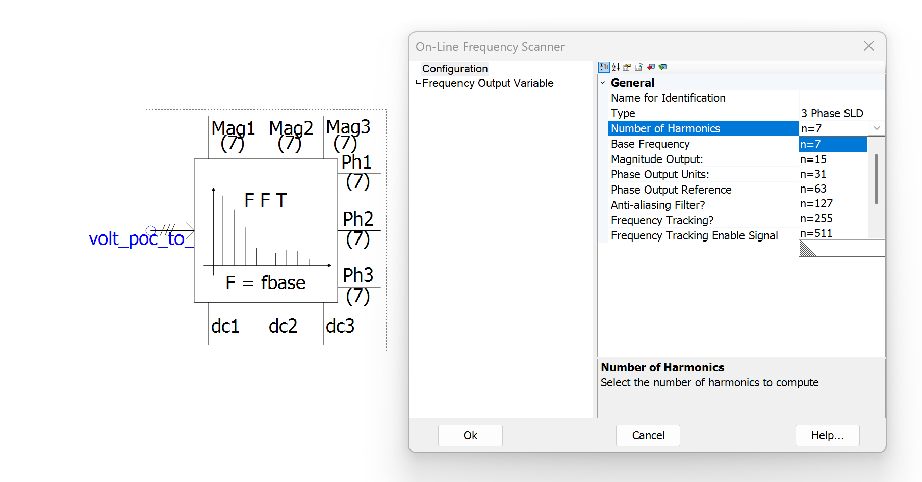
FFT frequency measurement
By default, the On-Line Frequency Scanner component within smiby which performs a Fast Fourier Transform (FFT) of the frequency measurement uses 7 harmonics for sampling (from smiby versions v24 and greater). For most simulations, this should be sufficient. However you may wish to increase this for some simulations where you may observe false positives for system collapse due to extreme aliasing. Note that increasing this sampling rate will be computationally demanding and may increase simulation time.
Updating smiby to a new version
Updating smiby may overwrite any of your custom modifications to smiby. In general, we recommend not making any changes to the smiby block or OEM libraries so that newer versions may be accommodated easily.
Revision history
Version 26 | 19 June 2026
Fixed- Fixed double up of base current scalar value causing Iqpos, Iqneg, Idpos and Idneg to be expressed on incorrect base value if smiby's single phase current base value is changed from the default of
1[A].
Version 25 | 7 May 2026
New- Released first version of independent control channel block (v1).
- Now supports single phase voltage playback.
- Added support for
FREQ_OSCILCommand (added frequency oscillation support and FQ angle measurement channel). - Added three phase RMS current at point of connection measurement channel.
- Point of connection circuit breaker can now be open or closed at a specified time, using the new
CONTROL_CB_POCCommand. - Added angle [degrees] at Thévenin equivalent source terminals measurement channel.
- Increased number of smiby control channels from 12 to 24.
- Added new output channels to output fault impedance magnitude and X/R ratio for
SIMPLEFAULTandVDISTURBANCEcommands.
- Updated Python script for updating smiby to automatically create the required
.cfgfiles (in addition to migrating the existing smiby configuration). - Description of base voltage field now states that it is a line-to-line voltage.
- Description of active power field now states that this value is overridden by the active power in the gridmo web-app project's active power field.
- Fixed all PSCAD build warnings and updated parameters to support PSCAD™ v5.1.0 (disabled module parameters argument set to
Default). - The frequency used within smiby's calculations now uses the Fref signal for the Thévenin source, rather than FFT readback, for better stability of Zsource during faults, now that Lsource varies with frequency by default. This should improve benchmarking under low SCR conditions with other RMS software packages e.g. PSS®E.
- Network frequency dependence was incorrectly turned on by default (despite the setting being set to
NOby default). Logic was also updated, see above. - Fixed incorrect base conversion for single phase current (single phase current outputs were in kA, not A).
- Fixed incorrect base conversion for sequence components of POC current e.g.
I1,I2andI0(sequence components were in kA, not p.u. on the specified base) - note this does not affect reactive or active sequence current e.g.Iq1orId1etc. - Fixed
SIMPLEFAULT, FZ=whereFZ=is not a percent (e.g. specified fault ohms) from always applying a bolted fault.
Version 24 | 20 January 2026
New- Added FFT block for calculating the magnitude of oscillations at a particular frequency for oscillation rejection tests.
- Removed stability resistor and circuit breaker for speed improvements as they are no longer required from gridmo Engine versions > 1.5.0.
- Changed the breaker closed resistance of all internal circuit breakers to 0.006 ohms for speed improvements as ideal circuit breakers are no longer required from gridmo Engine versions > 1.5.0.
- Decreased sampling rate of all On-Line Frequency Scanner components from 31 harmonics to 7 harmonics for speed improvements, as 31 harmonics are only required in rare instances.
- Replaced distance factor circuit breakers with variable impedances of very high/minimum impedance to act as circuit breakers for speed improvements.
- Replaced VDIST_OV circuit single phase circuit breakers with variable impedances of very high/minimum impedance to act as circuit breakers for speed improvements.
- Added logic to fault calculations which was causing a rare singularity error when the fault impedance is 1 ohm.
Version 23 | 5 August 2025
Improvements- Updated
VDISTURBANCEcalculation methodology to have higher accuracy on target residual voltage when applying faults with very low X/R ratios.
Version 22 | 2 July 2025
New- Added output channels for instantaneous single-phase voltage and currents.
- Added new parameter to allow direct control of the point of connection circuit breaker.
- Added new parameter to enable/disable high frequency sampling (1 kHz) for all point of connection metering channels - only typically used for tests which are sensitive to aliasing, such as voltage oscillation tests.
- Updated smiby default parameters to better align with gridmo's WECC-Solar model, default SCR raised from 3 to 10, all smiby base values updated to align with a typical 175 MW solar farm.
- Increased sampling rate of point of connection FFT frequency measurement from 7 harmonics to 31, to increase sampling rate to prevent false positives for system collapse due to extreme aliasing caused by the low sampling rate.
- Changed the impedance of all internal circuit breakers from 0.0005 ohms to 0 ohms to prevent slight benchmarking mismatches under really high SCR conditions (or really low base voltages).
Version 21 | 22 May 2025
New- Added functionality for unbalanced overvoltage disturbances.
- Added zero sequence impedance specification in
Zero sequence impedancetab underExternal impedanceusing user input for R0/R1 ratio and X0/X1 ratio.
- Switched on over-voltage snubber circuit by default.
- Added large resistances to prevent rare singularity error on point of connection circuit breaker switching commands.
- Set maximum absolute value capacitance to avoid singularity errors during initialisation where unbalanced overvoltage disturbances are enabled.
Version 20 | 25 April 2025
New- Added circuit breaker to the point of connection for asset switch-off tests.
- Added output channels for positive and negative sequence ratios (Ipos/Vpos and Ineg/Vneg).
- Added minimised plots for POC metering signals and all frequently used smiby channels - to help with model debugging.
- smiby can now support angle playback and voltage oscillation rejection tests with phase-angle modulation at the same time.
- Fixed angle playback logic for calculating infinite bus angle (angle value was previously incorrectly doubled - but only affects projects which did not use the default infinite bus angle of
0). - Moved
Apparent power base [MVA]field toAdvancedtab in smiby parameters and renamedBase valuestab toProject settings. - Fault impedance for a phase to phase fault was incorrectly double the desired impedance (other unbalanced fault types not affected).
Version 19 | 4 November 2024
- Fixed incorrect base value applied to positive/negative reactive current (IQ) and positive/negative active reactive current (ID), output channel unit is now consistent with total IQ and ID.
Version 18 | 31 October 2024
- Changed to integer version number (rather than linking smiby version to the version of the engine when it was updated).
- Added positive, negative and zero sequence voltage and current output channels.
- Fixed incorrect unit conversion on positive/negative reactive current (IQ) and positive/negative active reactive current (ID) output channels (was radians, should have been degrees).
- Low SCR initialisation mode now on by default for new smiby blocks added to a workspace.
- Added large resistances to prevent rare singularity error on
SIMPLEFAULTandVDISTURBANCECommands. - Pre-insertion resistance setting (for
VDISTURBANCE) and distance factor setting (for all faults) was greyed out unless faults were enabled - now always available. - Replaced non-linear pre-insertion resistance mode (for
VDISTURBANCE) with automatic snubber circuit which auto-calculates impedances required to achieve critical damping (based on the SCR), with a non-linear resistance ramp-out to prevent benchmarking mismatch during the disturbance. - Fixed inductive kickback experienced on some models with transmission line blocks (caused by
VDISTURBANCECB opening at any current incorrectly set to true, rather than a zero crossing).
Version 1.4.13.2 | 13 May 2024
- smiby's automatic infinite bus voltage not used to bias relative voltage steps.
- smiby's automatic infinite bus voltage mode incorrectly applies a fixed ramp rate to all subsequent voltage changes in a simulation.
Version 1.4.13 | 7 May 2024
- Added automatic infinite bus voltage calculation capability.
Version 1.4.12 | 15 April 2024
- Expanded low-SCR initialisation mode options. New modes include infinite bus voltage ramps, and infinite bus voltage and SCR ramps.
Version 1.4.11 | 20 March 2024
- Updated power factor calculation logic to improve handling for indeterminate cases (0/0).
To see the changelog for older changes to this model, please see the main gridmo change log here.