Example: How to merge multiple PSS®E plant models into a network model
Example version: v4
Software required:

Background
Utilities and system operators create and maintain models of their electrical network which accurately represent existing network behaviour. These network models are often created using PSS®E, supporting systems which take snapshots of real-world operating conditions and manual 'massaging' to ensure case stability. These network models can then be made available to proponents (e.g. AEMO | Policy on provision of network data).
However, utilities may only provide a model which is an accurate representation of existing behaviour. If you want to create a network model which represents future behaviour, you may need to modify the existing network model with known upcoming network augmentations (e.g. new generating systems which are under constructions and will soon be online, new transmission lines or load growth/decline).
This example shows how you can augment a network model by merging multiple future plant models and redispatching the network model. The post-augmentation network model can then be used in other grid code studies (e.g. NER Chapter 5 Typical Generator Performance Standards (GPS)) to investigate the impact of a proposed generator.
For clarity, this example involves merging and dispatching generators which are already committed and which are not your proposed generator.
Merging plant models and adjusting dispatch
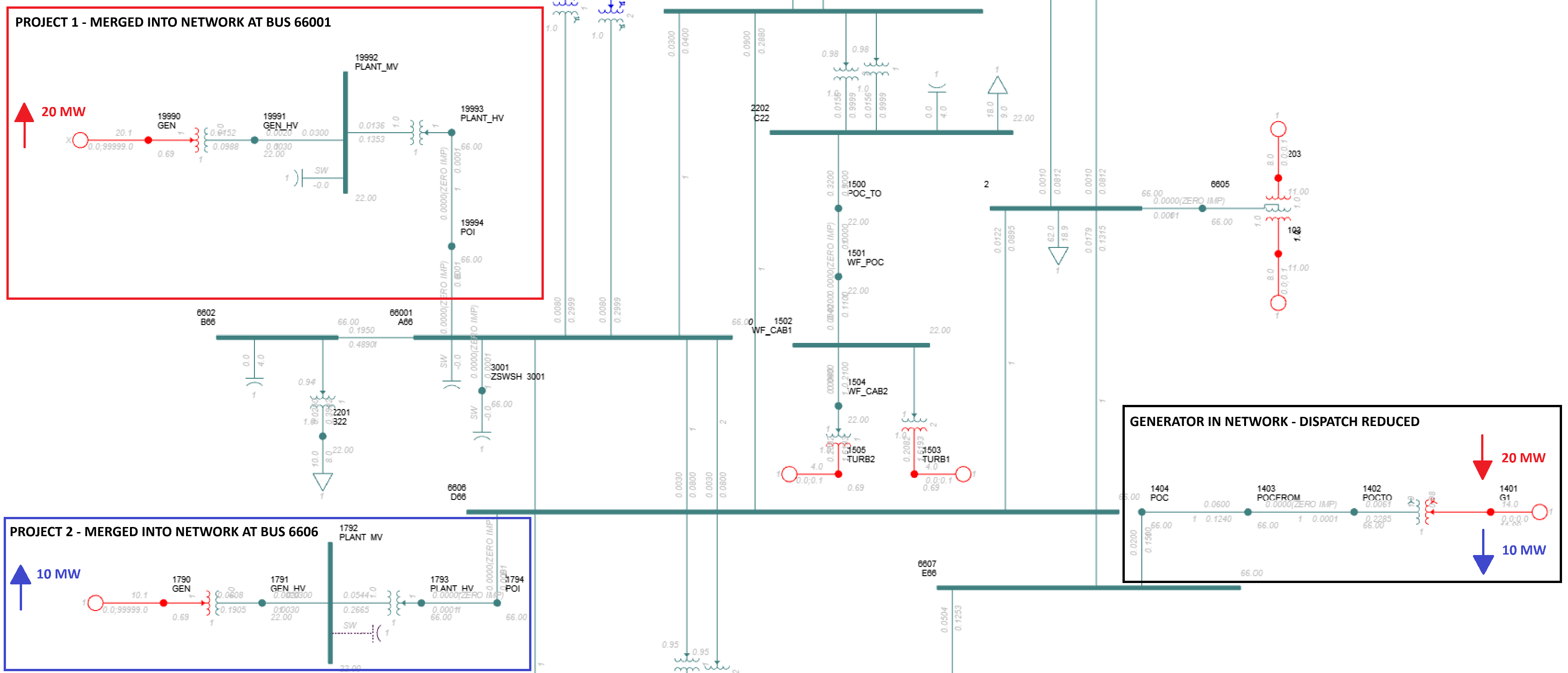
In this example, we have a network model which represents existing network behaviour at peak load during winter. We would like to create a network model which represents the network 12 months in the future when the peak load during winter is approximately the same but two new solar farms have finished construction and are operating. These two new solar farms are the following:
- Project 1 | Rated maximum active power = 20 MW | Forecasted winter dispatch = 10 MW
- Project 2 | Rated maximum active power = 40 MW | Forecasted winter dispatch = 20 MW
In this example network, there is negligible net load growth and there is a market dispatch mechanism. Therefore, the addition of this new solar generation will displace other generation in the network. When deciding which generators to dial down to accommodate the new generation, you want to choose the generators which would most likely be dialed down in the real-world. Depending on the type of network, factors in this decision may include:
- Energy market bid prices (i.e. higher priced bids are displaced by lower priced bids)
- Local constraints and curtailment
- Planned decommissioning
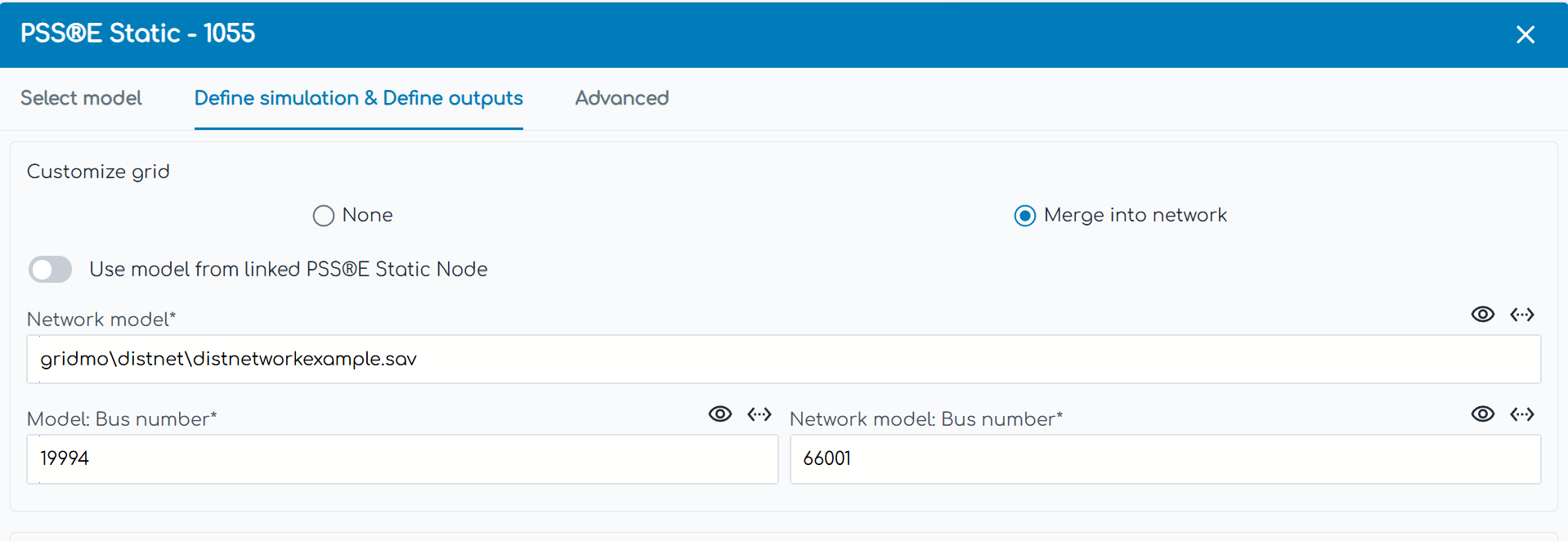
Merge project 1 model
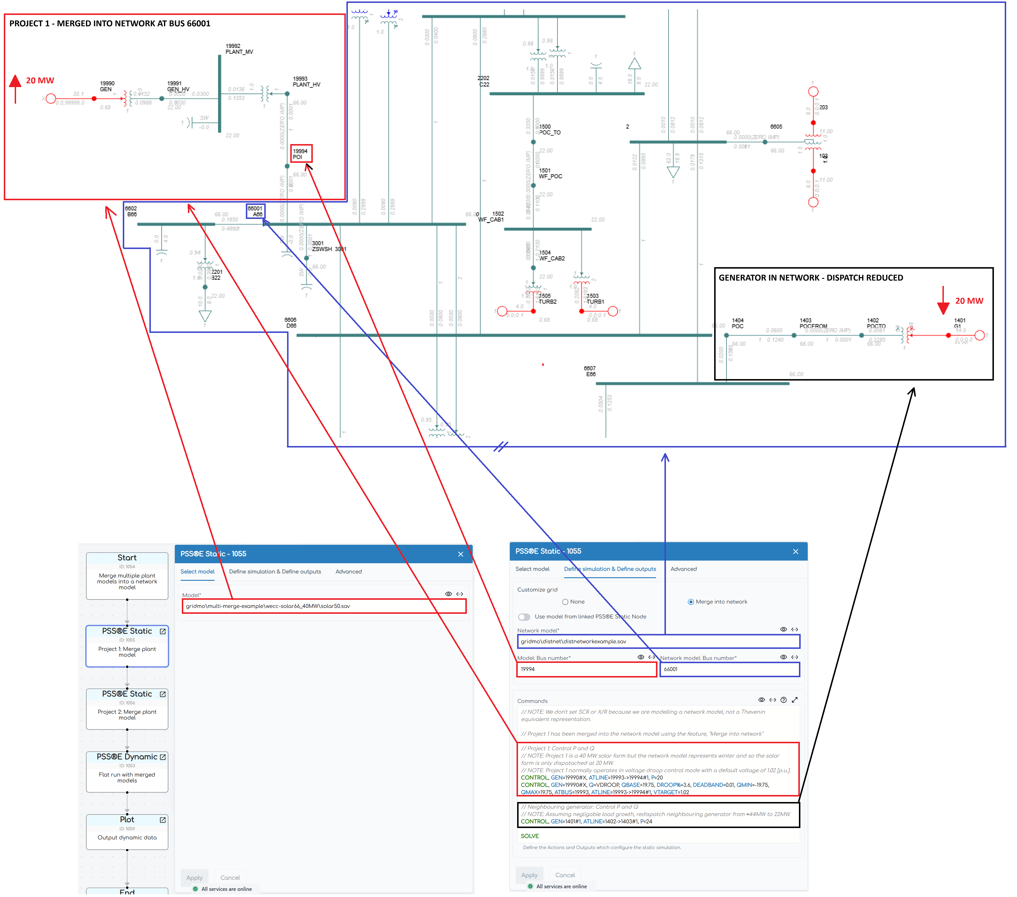
Merge project 1 model in PSS®E Static Node using gridmo's "Merge into network" feature.
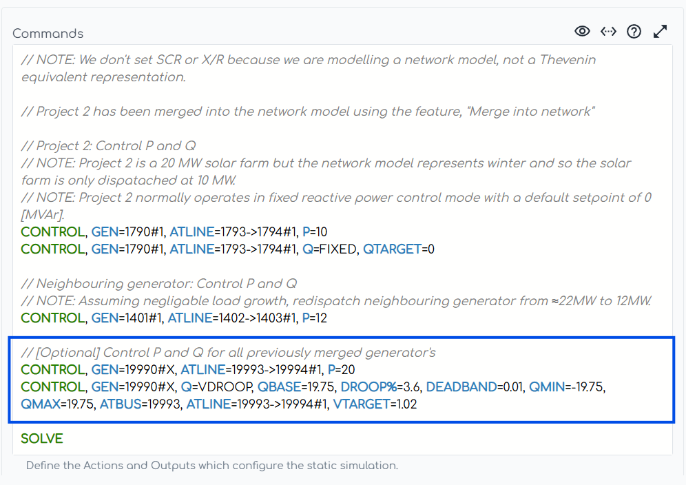
Control the dispatch of the newly merged project
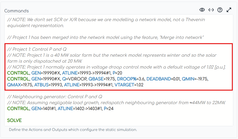
To choose an appropriate dispatch level of your merged model, you may wish to look at the generation levels of nearby generators in the network.
Redispatch marginal generator in the region to maintain overall generation level in the network
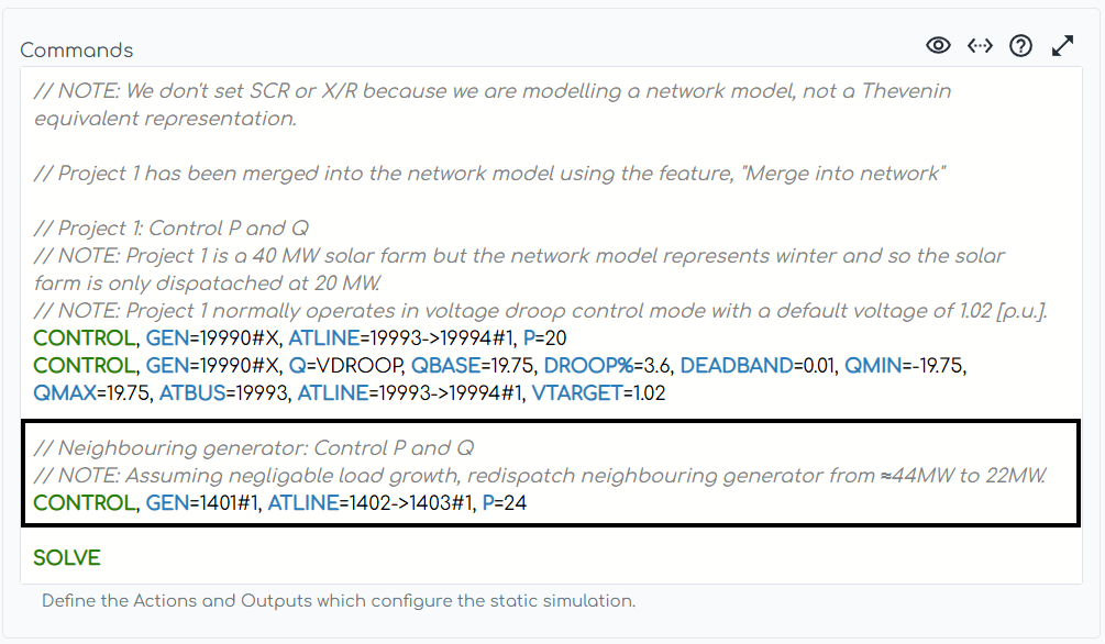
When deciding which generators to dial down, you could consider the following:
- The location of the generator relative to the merged model (e.g. reducing generation in a different region to your merged model may significantly affect interconnector flows and the scenario being studied).
- The average market price of the electricity generated by type of generator (e.g. batteries may generally be more expensive than solar or wind). It is reasonable to expect that a generator providing cheaper electricity will displace a more expensive generator (i.e. the marginal generator).
Merge project 2 model
Same concepts as above with one addition:
Redispatch all previously merged projects
The more SMIB models you merge into the network case, the more inaccurate their dispatch will be from the PSS®E Static Node which dispatched them (as each subsequent merged model will affect the load flow slightly). To ensure the dispatch matches the desired output, it is good practice to redispatch all previously merged SMIB models in the final PSS®E Static Node in your Run.
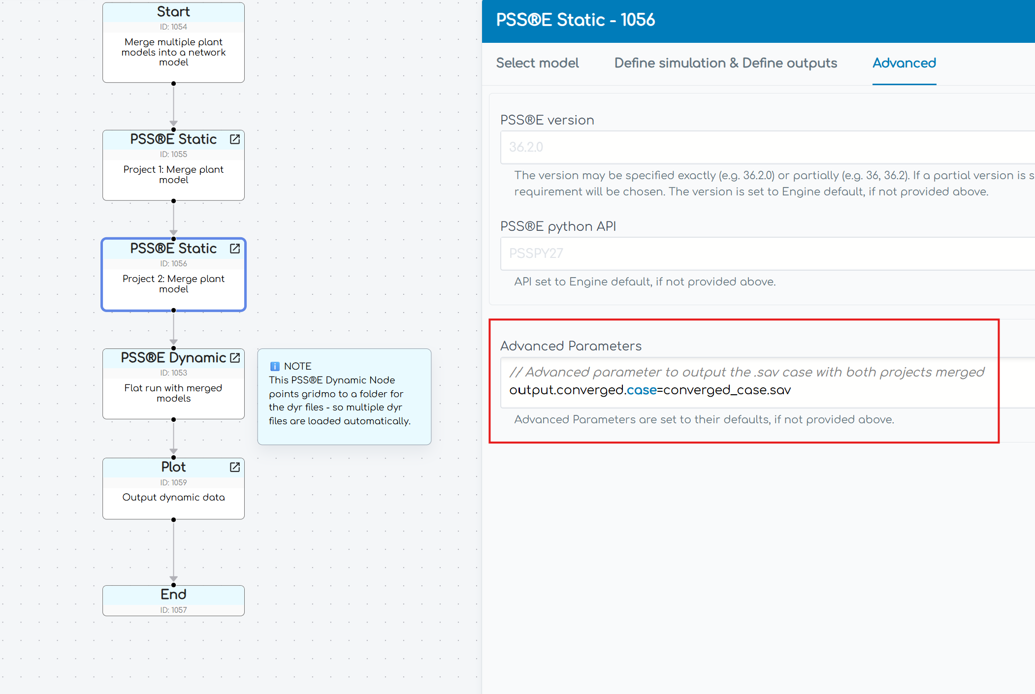
Output network case with merged projects
After merging both projects, you can extract the network case with both projects merged by using the Advanced tab of the last PSS®E Static Node in your Run. Add the parameter output.converged.case=[Enter .sav case name here].sav in the Advanced Parameters field as follows:
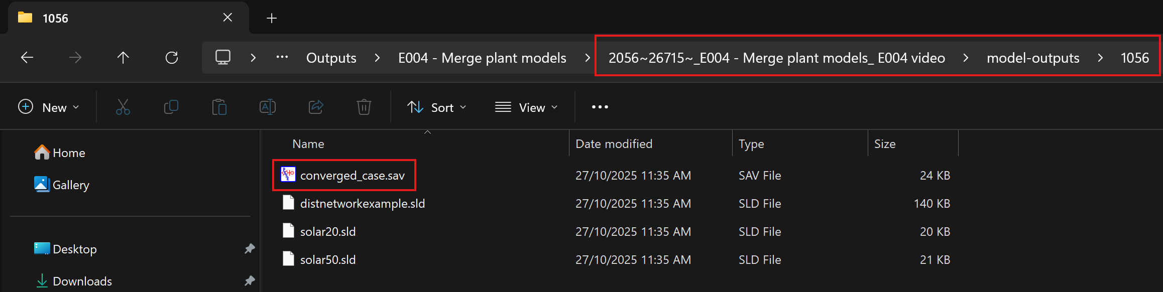
The updated network case will appear inside your Outputs folder for this simulation in a folder called model-outputs, which contains a folder numbered by the Node ID of the PSS®E Static Node outputting the updated network case:
Alternatively, you can also extract the updated network case by navigating to the all-temp folder in the Outputs folder for this simulation. Within the all-temp folder for the PSS®E Dynamic Node, it will contain the updated .sav case named solved_case.sav.
Revision history
Version 4 | 13 November 2025
Improvements- Added command
output.converged.caseto theAdvanced Parametersin PSS®E Static Node1056to output the updated network case with the merged projects.
- Fixed spelling errors.
- Updated example to redispatch nearby generator (at bus
1401) from 24 MW to 14 MW after adding 10 MW project, instead of 24 MW to 12 MW.
Version 3 | 12 October 2025
Improvements- Added subplots in Plot Node
1059to show voltage and frequency at network buses 34502, 6604 and 6606. - Updated example to merge a 20 MW solar farm and a 10 MW solar farm, but not the 175 MW solar farm model.
- Removed the Loop: Start Node which defined network faults. Simplified the example to only demonstrate a flat run.
- Removed all subplots for 175 MW solar farm model.
Version 2 (v1.4.15.6) | 23 July 2024
- Updated Sticky Node helper text in example.
Version 1 (v1.4.15) | 20 June 2024
- First release of example file.