Template: Southern Company Model Submittal Requirements for Transmission Connected Inverter-Based Resources
Version: 1
Last updated: 6 April 2025
Country:

US
Software required:
Source: Southern Company | Model Submittal Requirements for Transmission Connected Inverter-Based Resources | Version 3 | 7 March 2025

Before running this template, complete the following:
- Configure your Global Variables and Scenario Variables using gridmo's Model setup template.
- Add this template to your project.
- Configure the additional Global Variables marked as "[Unique to Southern Company template]".
- As outlined in section 4, if your SCR and X/R ratio at the connection point is unknown, use the default values of
$min_scr= 5 and$min_xr= 5. - Ensure source energy is 100% for tests 4.1.4-2 and 4.1.10-1. See below for details.
- By default, gridmo includes one legend per plot. If you would like one legend per subplot, you will need to update your output channels to include the desired legend name, as shown below.
-cfbacdbdda42200383b92cbe517bc295.png)
-f23d5a595580639564e3abbd8554ba6a.png)
Background
To comply with FERC Order 2023, Southern Company Transmission (SCT) requires submission of the following three simulation models for all inverter-based resources (IBRs) connecting to the Southern Companies’ Transmission System:
- PSS®E standard library models (i.e. 'generic' models)
- PSS®E user-written models (i.e. 'user-defined' models)
- PSCAD™ models
In order to ensure usability, robustness and accuracy of these models, Southern Company requires interconnection customers to meet the Model Submittal Requirements outlined in this template.
Configuration
3 Model requirements
The purpose of section 3 is to ensure that the submitted models adequately represent your generating system (e.g. correct aggregation methodology has been used), are compatible with the power systems versions currently used by Southern Company (e.g. PSS®E v35) and are appropriately formatted and documented (e.g. model supporting documentation shall be provided).
These requirements should be met prior to any studies being completed. See our best practices on file management which also meet the expectations of Southern Company.
4.1.1 Initialization tests
The purpose of Section 4.1.1 is to demonstrate your model's ability to initialize and run a flat run in a robust manner.
4.1.2 Balanced fault ride-through tests
The purpose of Section 4.1.2 is to confirm your generating system's response during and after balanced faults.
4.1.3 Small voltage disturbance (SVD) tests
The purpose of Section 4.1.3 is to confirm your generating system's response during and after small voltage disturbances.
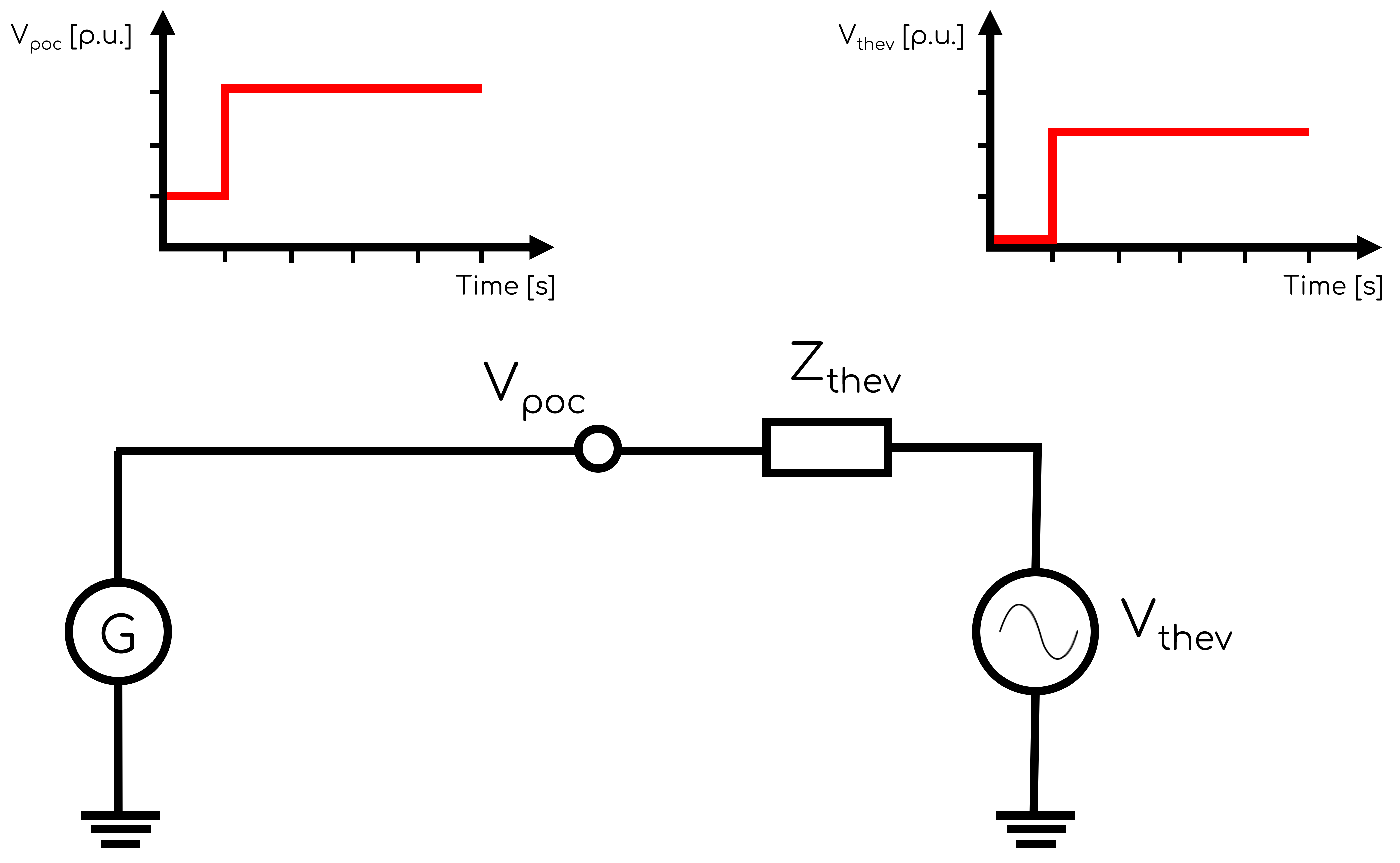
There are three methodologies to apply the voltage profile shown in Figure 2:
- Option 1: Change Vref in the PPC.
- Option 2 [Selected option]: Control the Thevenin equivalent voltage source (i.e. voltage playback).
- Option 3: Apply shallow faults for undervoltages and insert small capacitors for overvoltages.
Although Option 1 is provided as the example in the document, this option was not used due to the additional complexity of calculating the correct Vref value based on the plant's Q(V) droop curve and the Thevenin equivalent impedance. Option 2 was chosen due to its simplicity.
4.1.4 Small frequency disturbance (SFD) tests
The purpose of Section 4.1.4 is to confirm your generating system's response during and after small frequency disturbances.
Step 1 - Ensure source energy is 100% for test 4.1.4-2
As outlined in note 17, you must ensure that your generating system "...shall be operated at 50% Pmax with the capability to produce up to Pmax during the low frequency event." This may require modification of the default model settings. Note that source energy behaviour at initialization may be different depending on your OEM model. There is often a control setting in the model which can choose between whether source energy is initialized at the initial active power or set directly by the user or alternatively you can explicitly increase the source energy to max at the start of the simulation (i.e. AT=0). The relationship between source energy and terminal active power [MW] of a generating unit is typically non-linear and may be specific to particular OEM models, especially for PSCAD™ wind turbine models (i.e. wind speed v.s. active power).
- Tests are conducted using a playback generator with infinite inertia.
- All frequency 'steps' are completed at a 4Hz/s ramp rate. Instantaneous frequency changes are not realistic.
- Initial Vpoc is not provided. It is assumed to be 1.0 [p.u.].
4.1.5 Voltage or power factor (V/PF) step response tests
The purpose of Section 4.1.5 is to demonstrate your model's ability to operate in different reactive power control modes (e.g. voltage control mode and power factor control mode).
Step 1 - Choose PFref values
Choose PFref values which correspond to power factors of +0.95 and -0.95. Note that PFref values may be in different units depending on your OEM model (e.g. radians, degrees, unitless). If required, edit the PFref Commands in the relevant PSS®E Dynamic and PSCAD™ Nodes.
Depending on your control system gains and rate limiters, you may need to increase the duration between Vref/PFref steps and the simulation time to see the desired reactive power response.
4.1.6 Active power step response tests
The purpose of Section 4.1.6 is to demonstrate your model's ability to operate in active power control mode.
Depending on your control system gains and rate limiters, you may need to increase the duration between Pref steps and the simulation time to see the desired active power response.
4.1.7 High voltage ride-through (HVRT) tests
The purpose of Section 4.1.7 is to demonstrate your model's ability to operate in high voltage ride-through mode and to ride through a large overvoltage disturbance.
- Tests are conducted using a playback generator with infinite inertia.
- Initial SCR is to be set as "N/A" and is not provided. This was assumed to mean SCR should be set as infinite (i.e. Vthev = Vpoc, such that the voltage profile using the playback will be the same at the connection point).
4.1.8 Low voltage ride-through (LVRT) tests
The purpose of Section 4.1.8 is to demonstrate your model's ability to operate in low voltage ride-through mode and to ride through a large undervoltage disturbance.
- Tests are conducted using a playback generator with infinite inertia.
- Initial SCR is to be set as "N/A" and is not provided. This was assumed to mean SCR should be set as infinite (i.e. Vthev = Vpoc, such that the voltage profile using the playback will be the same at the connection point).
We often don't recommend projects use Thévenin equivalent voltage source playback for very low voltage dips (e.g. <10% residual voltage) which has been known to cause unrealistic and undesirable generating systems responses. Given the document has explicitly requested the test use the playback methodology, this methodology has been used. However, if you see unrealistic and undesirable responses, you may want to not use SCR = infinite and create the same voltage profile with the following two events:
- A fault impedance applied at 10 seconds for a duration of 320ms to model the lowest voltage dip.
- A Thévenin equivalent voltage source playback starting at 3.32 seconds to model the remainder of the voltage dips.
4.1.9 High frequency ride-through (HFRT) tests
The purpose of Section 4.1.9 is to demonstrate your model's ability to ride through a large overfrequency disturbance.
- Tests are conducted using a playback generator with infinite inertia.
- By default the PSCAD™ Node is disabled. It is often very uncommon to conduct network-wide PSCAD™ studies for large simulation times (e.g. > 300 seconds) due to the enormous simulation time. Therefore, assessing SMIB performance for a test which will most likely not be performed on the model in the future is therefore of little value. Nevertheless, this test may always be included by enabling the PSCAD™ Node.
4.1.10 Low frequency ride-through (LFRT) tests
The purpose of Section 4.1.10 is to demonstrate your model's ability to ride through a large underfrequency disturbance.
Step 1 - Ensure source energy is 100% for test 4.1.10-1
As outlined in note 18, you must ensure that your generating system "...shall be operated at 50% Pmax with the capability to produce up to Pmax during the low frequency event." This may require modification of the default model settings. Note that source energy behaviour at initialization may be different depending on your OEM model. There is often a control setting in the model which can choose between whether source energy is initialized at the initial active power or set directly by the user or alternatively you can explicitly increase the source energy to max at the start of the simulation (i.e. AT=0). The relationship between source energy and terminal active power [MW] of a generating unit is typically non-linear and may be specific to particular OEM models, especially for PSCAD™ wind turbine models (i.e. wind speed v.s. active power).
- Tests are conducted using a playback generator with infinite inertia.
- By default the PSCAD™ Node is disabled. It is often very uncommon to conduct network-wide PSCAD™ studies for large simulation times (e.g. > 300 seconds) due to the enormous simulation time. Therefore, assessing SMIB performance for a test which will most likely not be performed on the model in the future is therefore of little value. Nevertheless, this test may always be included by enabling the PSCAD™ Node.
4.1.11 Short circuit ratio (SCR) tests
The purpose of Section 4.1.11 is to demonstrate your model's ability to ride through a series of balanced faults and subsequent SCR changes. This test simulates faults being applied and being cleared such that the thevenin equivalent impedance increases (i.e. SCR drops).
4.1.12 Protection verification tests
The purpose of Section 4.1.12 is to confirm that some form of voltage and frequency protection exists and its behaviour is as expected.
- Tests are conducted using a playback generator with infinite inertia.
- Test 4.1.12-1 and 4.1.12-2: Initial SCR is to be set as "N/A" and is not provided. This was assumed to mean SCR should be set as infinite (i.e. Vthev = Vpoc, such that the voltage profile using the playback will be the same at the connection point).
4.1.13 Reactive power capability tests
The purpose of Section 4.1.13 is to identify your generating system's reactive power capability while operating across a range of different conditions (e.g. active power outputs and connection point voltages).
- Initial SCR is to be set as "N/A" and is not provided. This was assumed to mean SCR should be set as infinite (i.e. Vthev = Vpoc, such that the voltage profile using the playback will be the same at the connection point).
- There appears to be a contradiction in methodology. There are two potential described methodologies for this test, as outlined below. We have selected Option 2.
- Option 1: Initialize at an operating point known to be within the connection point limiters (e.g. Vpoc = 1.0 [p.u.], Ppoc = Pmax, Qpoc = 0 MVAr). Then apply a disturbance such that the generating system finishes the simulation at the desired Vpoc and Qpoc values. This methodology is implied by the statement, "Grid Initial Condition: Apply the voltage at the POI as shown in the table above (i.e. use the playback model in PSS®E and controllable voltage source in PSCAD™ at the POI)."
- Option 2 [Selected option]: Initialize at the operating point described in the table (e.g. Vpoc = 0.9 [p.u.], Ppoc = Pmax, Qpoc = 0.7 x Qmax). Then run a flat run. This methodology is implied by the pass/fail criteria which implies that the dynamic simulation should be a flat run by requiring that the simulation "...remain flat during the simulation run." Note that the behaviour of the model during this test depends on your OEM model. Be careful of some OEM models which may initialize outside of their connection point limits and not raise initialization errors.
4.2.1 Unbalanced fault tests
The purpose of Section 4.2.1 is to confirm your generating system's response during and after unbalanced faults.
- High impedance 1LG fault: A "single-phase-to-ground fault with a fault impedance equal to the grid impedance" will not cause "50% voltage retained at the POI" since the POI measurement is often a 3-phase representation. We have assumed that the methodology of applying the shallow single phase fault will cause approximately a 50% voltage retained on the faulted phase.
We have not yet included automated tests for the requirement, "The IBR unit’s incremental positive and negative sequence reactive current injections shall meet the requirements in Section 5.5.2 of SCT’s Interconnection Requirements for Transmission Connected Inverter-Based Resources [3]" since we need to confirm the methodology required. Automated assessment of this requirement will be added in the future.
4.2.2 Phase angle change tests
The purpose of Section 4.2.2 is to confirm the ability of your generating system to ride-through phase angle changes at the connection point.
- We assumed that the voltage phase angle change was performed by controlling the Thevenin equivalent voltage source (i.e. angle playback). Note that all SMIB studies assume the reference angle is the Thevenin equivalent voltage source which therefore has an initial phase angle of 0°. Therefore, the initial phase angle at the connection point will be non-zero, depending on the initial operating condition (i.e. Vpoc, SCR), and will change ±25° relatively.
Assumptions
- We assume that SCR = (Minimum 3PH synchronous fault level / project rated active power).
- Supporting documentation like model documentation and checklist documentation is not included in this template. See Appendix B for a full list of items that you must include in a model submittal package of an interconnection customer.
- Both the "required" and "supplemental" tests are included in the template. By default, both tests are selected because Southern Company states the supplemental tests "...are recommended to be included."
- By default, each Plot Node has x-axis: Min [seconds] set as 5 seconds to exclude the PSCAD™ initialization time and allow for better scaling to show the test results. This may be changed, or you may submit the .html files as well to allow the reviewer to zoom in on the initialization period, as required.
- It is assumed that the generic and user-defined models can use the same common .sav case file for PSS®E Static Nodes.
- The reactance to resistance ratio (i.e. X/R ratio) of all applied faults is assumed to be 3.
- The requirement that "Active power, reactive power, and voltage values shall reasonably match between PSS®E standard library, PSS®E UDM, and PSCAD™ models at the POI" is subjective. Given this subjective nature, we have not included error band Commands on the subplots and instead you must check this manually.
- The requirement that "the plant...shall have a stable and well-damped response" is subjective. Given this subjective nature, we have not included damping ratio Commands on the subplots and instead you must check this manually.
- There are two recovery time calculation methodologies in this document, as outlined below. For simplicity the recovery time calculation methodology for the entire document is considered from the disturbance clearance time (i.e. Methodology 1 below).
- Methodology 1 (4.1.7 and 4.1.8): "If active power is reduced, it shall recover to the pre-disturbance value 1.0 second after the disturbance..."
- Methodology 2 (4.1.2 and 4.2.1): "After fault clearing and voltage recovery within the normal range, the active power recovery time to the pre-fault value shall be 1.0 second..."
- Momentary cessation mode is defined where terminal current goes to 0 (i.e. current blocking mode). Therefore, a check whether this mode is activated would be to either check for Pgen=Qgen=0 or Igen=0. However, checking for Pgen=0 has issues where during deep faults, the plant could be in reactive power priority mode and therefore Pgen will go to 0, but the system will not be in momentary cessation mode - therefore causing false positives in the Analysis Node. Additionally, checking Igen=0 can cause issues because current output on a line is not natively supported in PSS®E and instead must be calculated whereby
I [p.u.] = S [MVA] / (V [p.u.] * SBASE [MVA])- at very low voltages this may cause issues and again causing false positive in the Analysis Node. We have therefore chosen a check of Qgen=0 during the disturbance as an indication of momentary cessation mode. Qgen=0 during a disturbance doesn't guarantee that the plant is in momentary cessation mode, but if the plant is in momentary cessation mode, it is guaranteed that Qgen=0. - This template includes only the tests from Section 4. More tests would be required to verify the requirements in Section 3 and Southern Company | Interconnection Requirements for Transmission Connected Inverter-Based Resources | 6 August 2023, such as:
- Southern Company | Model Submittal Requirements for Transmission Connected Inverter-Based Resources | Version 3 | 7 March 2025 - Section 3, Item 4. "The plant models shall have the capability to change the control mode to any control mode possible in the actual power plant (e.g., voltage control, reactive power control, or power factor control, etc.) with accessible and modifiable reference setpoints": Section 4 doesn't include tests in reactive power control mode.
- Southern Company | Interconnection Requirements for Transmission Connected Inverter-Based Resources | 6 August 2023 - 5.4.2, Table 5: Further tests would be required to verify damping ratio ≥ 0.3.
- Figure 13 shows sample subplots using the following units: Frequency [Hz], Voltage [p.u.], Active power [p.u.] and Reactive power [p.u.]. It is assumed that users would prefer active power and reactive power units to be MW and MVAr respectively, given this is a more common industry standard.
Sources
- Southern Company | Model Submittal Requirements for Transmission Connected Inverter-Based Resources | Version 3 | 7 March 2025
- Southern Company | Interconnection Requirements for Transmission Connected Inverter-Based Resources | 6 August 2023
Revision history
Version 1 | 6 April 2025
- First release.