Template: NYISO Electromagnetic Transient (EMT) Modeling Guideline
Template version: v1
Country:

US
Software required:
Source: NYISO | Electromagnetic Transient (EMT) Modeling Guideline | Version 2.0 | 24 June 2025

How to add this template to your project
- From within your gridmo project, open the flow dropdown and select 'Add flow'.
- Select the template you want to use and click 'Add to project'.

Background
The number and complexity of EMT models have increased during the energy transition. NYISO introduced this modeling guideline to ensure the quality of submitted EMT models. All EMT models submitted to NYISO must meet the guideline requirements and complete the model tests - noting that "EMT models for generation plants that utilize well established prime mover technology (non-IBRs, such as hydro turbine-generator, combined cycle units, nuclear units, etc.) are exempt from performing these tests and will be evaluated separately on a case-by-case basis".
Reference
Common assumptions
- General: Supporting documentation like "PSCAD Model Test Checklist" is not included in this template. See Section 6 for a full list of items that you must include in a model submission package.
- General: By default, each Plot Node has x-axis: Min [seconds] set as 3 seconds to exclude the PSCAD™ initialization time and allow for better scaling to show the test results. This may be changed, or you may submit the .html files as well to allow the reviewer to zoom in on the initialization period, as required.
- General: We have assumed that users only want plots to show phase to ground voltages for unbalanced tests.
- General: Where "test duration" hasn't been specified, we assume the simulation time is set such that there is 10 seconds of duration after the last test event (e.g. if a fault is applied at 5 seconds, the simulation time is 15 seconds).
- General: The reactance to resistance ratio (i.e. X/R ratio) of all applied faults is assumed to be the same as the X/R ratio of the Thevenin equivalent impedance for the initial operating condition.
- General: Where initial Vpoc has not been specified for a test, we have assumed "default connection point voltage [p.u.]" (i.e.
$default_poc_voltage). This can be set as 1.0 [p.u.] if desired. - Section 4.7: We assume that the Positive Sequence Phasor Domain (PSPD) tool being used is PSS®E.
- Section 4.7: The requirement that, "A qualitative criterion will be used to determine if the models are in good alignment and no quantitative criterion (e.g., signal envelopes, peak values, etc.) will be employed at this time" is subjective. Given this subjective nature, we have not included error band Commands on the subplots and instead you must check this manually.
- Section 7.2: "A single AC voltage source equivalent (Thevenin Equivalent) shall be connected at the POI to
represent the rest of the system and must reflect typical SCMVA at the POI". We assume that "typical" SCR is represented by
$max_scrand$max_xr. - Section 7.3: We have assumed the following units: Voltage [p.u.], Active power [MW], Reactive power [MVAr], rather than, "all values must be in put on the plant/device ICR or ICAR rating (as defined in IEEE 2800)". It is assumed that users would prefer active power and reactive power units to be MW and MVAr respectively, given this is a more common industry standard.
Test 1: Initialization tests
The purpose of Test 1 is to demonstrate your model's ability to initialize and run a flat run in a robust manner.
We assume that the initialization time of 5 seconds is based on a settling time calculation where the connection point values must settle within "±1% of their reference setpoint values" or ±1% of their base values, whichever is greater. The ±1% of base value requirement was introduced because certain operating conditions (e.g. Qpoc = 0 MVAr), "±1% of their reference setpoint values" can become a very small number (i.e. ±1% of 0 MVAr).
Test 2: Balanced fault ride-through
The purpose of Test 2 is to confirm your generating system's response during and after balanced voltage disturbances.
We assume that "driving point impedance" is the Thevenin equivalent impedance.
Test 3: Unbalanced fault ride-through
The purpose of Test 3 is to confirm your generating system's response during and after unbalanced voltage disturbances.
We assume that a fault impedance of "--" for LL faults is Zf=0.
Test 4: Overvoltage ride-through
The purpose of Test 4 is to confirm your generating system's ability to ride through overvoltage disturbances.
Test 5: Voltage reference setpoint change
The purpose of Test 5: Voltage reference setpoint change is to demonstrate your model's ability to operate in voltage control mode.
Test 5: Reactive power reference setpoint change
The purpose of Test 5: Reactive power reference setpoint change is to demonstrate your model's ability to operate in reactive power control mode.
Test 5: Power factor reference setpoint change
The purpose of Test 5: Power factor reference setpoint change is to demonstrate your model's ability to operate in power factor control mode.
Test 5: Grid voltage change
The purpose of Test 5: Grid voltage change is to confirm your generating system's response during and after small Thevenin equivalent reference changes (i.e. grid voltage disturbances).
- We assume the criterion, "15 second response time" refers to a "step response time" in accordance with Figure 5 of IEEE Std 2800™-2022.
- We assume the criterion, "15 second response time" only applies to the connection point reactive power response in accordance with section 5.2.2 of IEEE Std 2800™-2022.
Test 6: Active power reference ramp
The purpose of Test 6 is to demonstrate your model's ability to operate in active power control mode.
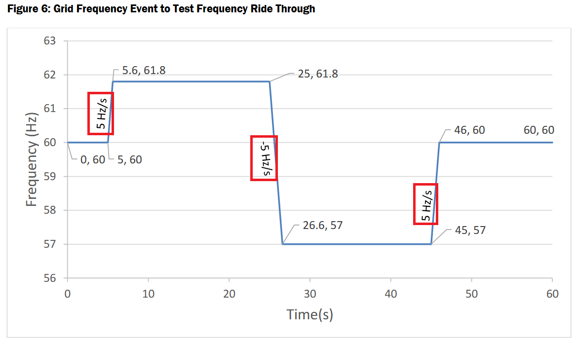
Test 7: Frequency ride-through
The purpose of Test 7 is to confirm your generating system's ability to ride through frequency disturbances.
The ramp rates in Figure 6, when calculated using the (time, frequency) values provided, are ± 3 Hz/s. However, Figure 6 annotations (as outlined in red in the image below) state ± 5 Hz/s. We assume that the (time, frequency) values provided in Figure 6 are correct and that the ramp rates are therefore ± 3 Hz/s, not ± 5 Hz/s.
Test 8: PFR and FFR
The purpose of Test 8 is to independently confirm your generating system's FFR and PFR control mode responses.
- Test #8-2 and #8-4 baseline response criteria: We assume that "No significant response for the over frequency step" means that the change in active power is ≤ 0.05 [p.u. on rated active power].
- Test #8-3 baseline response criteria: We assume that "with response time in line with values in Table 8 of IEEE2800" means that we should assess all of hte parameters in Table 8 (i.e. reaction time, rise time, settling time and damping ratio).
- Test #8-4 baseline response criteria: We assume that "No significant response for the over frequency step" is a typo and is actually meant to state "No significant response for the underfrequency step".
Test 9: Phase angle jump ride-through
The purpose of Test 9 is to confirm your generating system's ability to ride through angle disturbances.
Test 10: SCR changes and balanced faults
The purpose of Test 10 is to confirm the generating system's ability to ride through progressively decreasing SCR changes at the same time as balanced faults.
- We assume that all balanced faults are bolted faults.
Test 11: Over and under voltage protection verification
The purpose of Test 11 is to confirm your generating system has some form of voltage protection.
- We assume that tests are conducted at infinite SCR to ensure the desired voltage signal is played back directly at the connection point.
Sources
- NYISO | Electromagnetic Transient (EMT) Modeling Guideline | Version 2.0 | 24 June 2025
- IEEE Std 2800™-2022
Revision history
Version 1 | 13 October 2025
- First release.