Template: MISO Business Practices Manual (BPM-015) for Generator Interconnection
Template version: v1
NEW!Country:

US
Software required:
Source: MISO | BPM-015-r32 Business Practices Manual - Generator Interconnection | Version 32 | 15 December 2025

How to add this template to your project
- From within your gridmo project, open the flow dropdown and select 'Add flow'.
- Select the template you want to use and click 'Add to project'.

Background
The number and complexity of power system models have increased during the energy transition. MISO introduced Business Practices Manual BPM-015 to ensure the quality of submitted models. Appendix I contains the Inverter-Based Resource (IBR) modelling and submission requirements.
This template does not yet contain the tests from Appendix H. If you require these tests, please contact us.
Reference
Common assumptions
- General: Supporting documentation like a "Parameter Verification Report" is not included in this template. See Appendix I for a full list of items that you must include in a model submission package.
- General: The x-scale is outlined as, "All tests shall be run for a minimum simulation duration of 30 seconds and the results shall be plotted for the time from 0 to 30 seconds." By default, each Plot Node has x-axis: Min [seconds] set as 5 seconds to exclude the PSCAD™ initialization time and allow for better scaling to show the test results. This may be changed, or you may submit the .html files to allow the reviewer to zoom in on the initialization period, as required.
- General: The reactance to resistance ratio (i.e. X/R ratio) of all applied faults is assumed to be 3.
- General: The requirement, "Active, reactive, and voltage values shall reasonably match between standard library, PSS®E/TSAT UDM, and PSCAD™ models at the POM" is subjective. We have assumed the following quantitative error bands:
- Vpoc: Models must remain within an error band of ± 0.005 [p.u.] for 95% of samples after a 5 second initialization period.
- Ppoc: Models must remain within an error band of ± 1% x (Pbase) [MW] for 95% of samples after a 5 second initialization period.
- Qpoc: Models must remain within an error band of ± 1% x (Qbase) [MVAr] for 95% of samples after a 5 second initialization period.
- General: We have assumed the following units: Voltage [p.u.], Active power [MW], Reactive power [MVAr].
- General: The pass/fail criteria lettering doesn't make sense. For example, I-5.1.2 starts at (d) and I-5.1.3 jumps from (b) to (h). This lettering has therefore been ignored.
- I-4 Model Requirements: There are many model requirements outlined in this section for which there are no tests explicitly defined in Appendix I. We have not included additional tests to verify these requirements. Some examples of such requirements:
- I-4.1 General Requirements for All Models (3) - Reactive power control modes: This section states, "The models shall have the capability to change the control mode to any control mode possible in the actual power plant (e.g., voltage droop control, reactive power control, or power factor control, etc.) with accessible and modifiable reference setpoints". However, there are no tests explicitly defined in Appendix I which conduct reference setpoint changes.
- I-4.5 Requirements for PSCAD™ Models (6)(g): This section states that the models should "Support the PSCAD™ 'snapshot' feature". However, there are no tests explicitly defined in Appendix I which conduct snapshot tests.
- I-5.1.4, I-5.1.7, I-5.1.8, I-5.1.9: We have assumed that SCR of "N/A" refers to an infinite SCR.
- I-5.1.3, I-5.1.5, I-5.1.6: It is unclear whether the test should be conducted with or without thevenin equivalent impedance. The following references create confusion:
- The table describes "Infinite Bus Voltage" as "N/A" which implies no thevenin equivalent impedance (i.e. SCR is infinite).
- The table describes "SCR as "3" which implies thevenin equivalent impedance.
- The section "Grid Initial Condition" describes "Assume an ideal voltage source at the POM to represent the grid" which implies no thevenin equivalent impedance (i.e. SCR is infinite).
 We have assumed for these sections that the tests should be conducted with no thevenin equivalent impedance (i.e. SCR is infinite).
- The plotting requirements seem strange. It is stated, "Frequency, voltage, active power, and reactive power shall be plotted at the point of measurement (POM) in separate figures for each test (i.e., four figures for each test). Relevant Trip control signals shall be included in the related plot (e.g., frequency tripping shown on frequency plot)." However, this requirement would mean that Angle at the POC would not be plotted for an angle change test in I-5.1.9. We have therefore provided two sets of plots:
- "POC only" in accordance with this requirement.
- A more complete set of subplots monitoring the plant.
I-5.1.1 Initialization tests
The purpose of I-5.1.1 is to demonstrate your model's ability to initialize and run a flat run in a robust manner.
We assume that the initialization time of 5 seconds is based on a settling time calculation where the connection point active power and reactive power must settle within "±1% of their reference setpoint values" or ±1% of their base values, whichever is greater. The ±1% of base value requirement was introduced because certain operating conditions (e.g. Qpoc = 0 MVAr), "±1% of their reference setpoint values" can become a very small number (i.e. ±1% of 0 MVAr).
I-5.1.2 Balanced fault ride-through tests
The purpose of I-5.1.2 is to confirm your generating system's response during and after balanced voltage disturbances.
- PSS®E only natively supports three phase (3PH) faults. Three phase to ground (3PHG) are not natively supported. Therefore, for fair benchmarking with EMT studies, we have assumed 3PH faults.
- "An acceptable damping ratio is 0.3 or greater [5]" is unclear. The reference to IEEE2800 clarifies the definition of damping ratio, but does not reference for which channels the requirement applies. We have assumed that the damping ratio applies to Qpoc.
- "After fault clearing and voltage recovery within the normal range, the active power recovery time to the pre-fault value shall be within 1.0 second" is unclear. There is no definition of "normal range" and this is not a defined term in IEEE2800. IEEE2800 contains terms such as "continuous operation region", "mandatory operation region" and "permissive operation region", but these terms are not used. Therefore, it is not possible to determine at which time the recovery time calculation should begin. We have therefore the calculation begins "after fault clearing" and the phrase "and voltage recovery within the normal range" has been ignored.
- "the active power recovery time to the pre-fault value" is assumed to mean the time taken to return to 99% of the pre-fault value. Due to model numerical accuracy, it may never reach 100% of the pre-fault value.
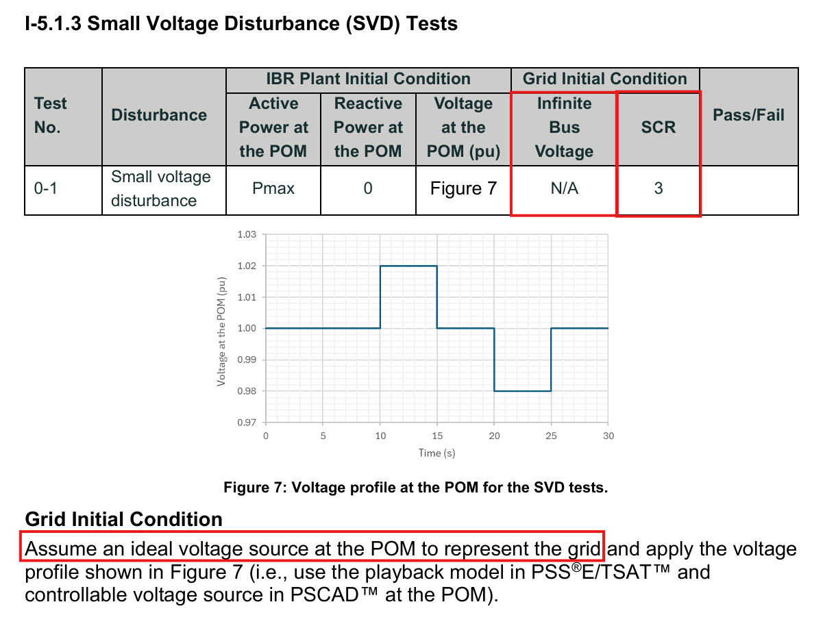
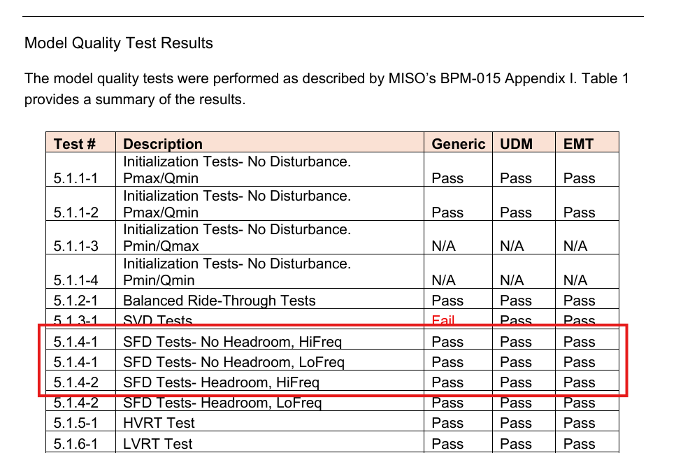
I-5.1.3 Small voltage disturbance (SVD) tests
The purpose of I-5.1.3 is to confirm your generating system's response during and after small voltage disturbances.
- "An acceptable damping ratio is 0.3 or greater [5]" is unclear. The reference to IEEE2800 clarifies the definition of damping ratio, but does not reference for which channels the requirement applies. We have assumed that the damping ratio applies to Qpoc.
I-5.1.4 Small frequency disturbance (SFD) tests
The purpose of I-5.1.4 is to confirm your generating system's response during and after small frequency disturbances.
- The initial voltage is unclear. The table states that "Voltage at the POM (pu)" shall be in accordance with "Figure 8 (b)". However, Figure 8(a) and Figure 8(b) shows frequency profiles. We have assumed an initial voltage of 1 [p.u.].
- We have assumed that Figure 8 (a) and Figure 8 (b) are applied for the test conditions listed in the table for I-5.1.4-1 and I-5.1.4-2 (i.e. total of four tests). This is opposed to Figure 8 (a) and Figure 8 (b) profiles each being applied for I-5.1.4-1 and I-5.1.4-2 respectively (i.e. total of two tests). This assumption appears to be confirmed by the table in the example results section.
- We have assumed that all frequency changes do not exceed a ROCOF of 5 [Hz/s]. This is the same ROCOF used in I-5.1.7 High-frequency ride-through tests.
- "An acceptable damping ratio is 0.3 or greater [5]" is unclear. The reference to IEEE2800 clarifies the definition of damping ratio, but does not reference for which channels the requirement applies. We have assumed that the damping ratio applies to Ppoc.
I-5.1.5 High-voltage ride-through (HVRT) tests
The purpose of I-5.1.5 is to confirm your generating system's response during and after large over voltage disturbances.
- "If active power is reduced, it should recover to the pre-disturbance value within 1.0 second after the disturbance" is assumed to mean the time taken to return to 99% of the pre-disturbance value. Due to model numerical accuracy, it may never reach 100% of the pre-fault value.
I-5.1.6 Low-voltage ride-through (LVRT) tests
The purpose of I-5.1.6 is to confirm your generating system's response during and after large under voltage disturbances.
- Using a Thévenin equivalent voltage source playback for very low voltage dips (e.g. < 0.1 [p.u.]) has been known to cause unrealistic and undesirable generating systems responses. Given the methodology explicitly says to "use the playback model", we have used the playback model but have changed the lowest voltage level from 0.00 [p.u] to 0.001 [p.u] to avoid the worst of the potential software instability issues. If your model observes such unrealistic and undesirable generating systems responses from the very low playback model voltage dip, we recommend replacing the first low voltage event with a 3PH bolted fault and use playback for the remaining events.
- "If active power is reduced, it should recover to the pre-disturbance value within 1.0 second after the disturbance" is assumed to mean the time taken to return to 99% of the pre-disturbance value. Due to model numerical accuracy, it may never reach 100% of the pre-fault value.
I-5.1.7 High-frequency ride-through (HFRT) tests
The purpose of I-5.1.7 is to confirm your generating system's response during and after large over frequency disturbances.
- "An acceptable damping ratio is 0.3 or greater [5]" is unclear. The reference to IEEE2800 clarifies the definition of damping ratio, but does not reference for which channels the requirement applies. We have assumed that the damping ratio applies to Ppoc.
I-5.1.8 Low-frequency ride-through (LFRT) tests
The purpose of I-5.1.8 is to confirm your generating system's response during and after large under frequency disturbances.
- "An acceptable damping ratio is 0.3 or greater [5]" is unclear. The reference to IEEE2800 clarifies the definition of damping ratio, but does not reference for which channels the requirement applies. We have assumed that the damping ratio applies to Ppoc.
I-5.1.9 Protection verification tests
The purpose of I-5.1.9 is to confirm that some form of voltage and frequency protection exists and its behaviour is as expected.
- Test 2: Using a Thévenin equivalent voltage source playback for very low voltage dips (e.g. < 0.1 [p.u.]) has been known to cause unrealistic and undesirable generating systems responses. Given the methodology explicitly says to "use the playback model", we have used the playback model but have changed the lowest voltage level from 0.00 [p.u] to 0.001 [p.u] to avoid the worst of the potential software instability issues. If your model observes such unrealistic and undesirable generating systems responses from the very low playback model voltage dip, we recommend replacing the first low voltage event with a 3PH bolted fault and use playback for the remaining events.
- Test 3 and 4: The initial voltage is unclear. The table states that "Voltage at the POM (pu)" shall be in accordance with "Figure 9 (c)" and "Figure 9 (d)". Firstly, Figure 9(c) and Figure 9(d) don't exist. Assuming they refer to Figure 13(c) and Figure 13(d), these figures show frequency profiles. We have assumed an initial voltage of 1 [p.u.].
- Test 3 and 4: Figure 13(c) and Figure 13(d) appear to show almost infinite ROCOF (far beyond realistic grid ROCOF of ≈5 [Hz/s]). Given these tests are protection verification tests, not ride-through tests, we have assumed a near infinite ROCOF requirement of ±10,000 [Hz/s] (i.e. 10 [Hz] change in 0.001 [ms]) to reflect what appears to be a step change in the provided figures.
I-5.1.10 Short circuit ratio (SCR) tests
The purpose of I-5.1.10 is to confirm your generating system's ability to ride through a series of balanced faults and subsequent SCR changes. This test simulates faults being applied and being cleared such that the thevenin equivalent impedance increases (e.g. SCR drops because lines are opening to clear a fault).
- The X/R ratio of the Thevenin equivalent impedance is unclear for initial conditions and throughout the test. We assume that the X/R ratio is constant throughout the test and remains as
$xr_min. - "An acceptable damping ratio is 0.3 or greater [5]" is unclear. The reference to IEEE2800 clarifies the definition of damping ratio, but does not reference for which channels the requirement applies. We are unable to make an educated guess on which signals this damping ratio should be applied. Therefore, we have not applied this damping ratio calculation in this test.
I-5.2.1 Quality and performance tests for PSCAD™ models only
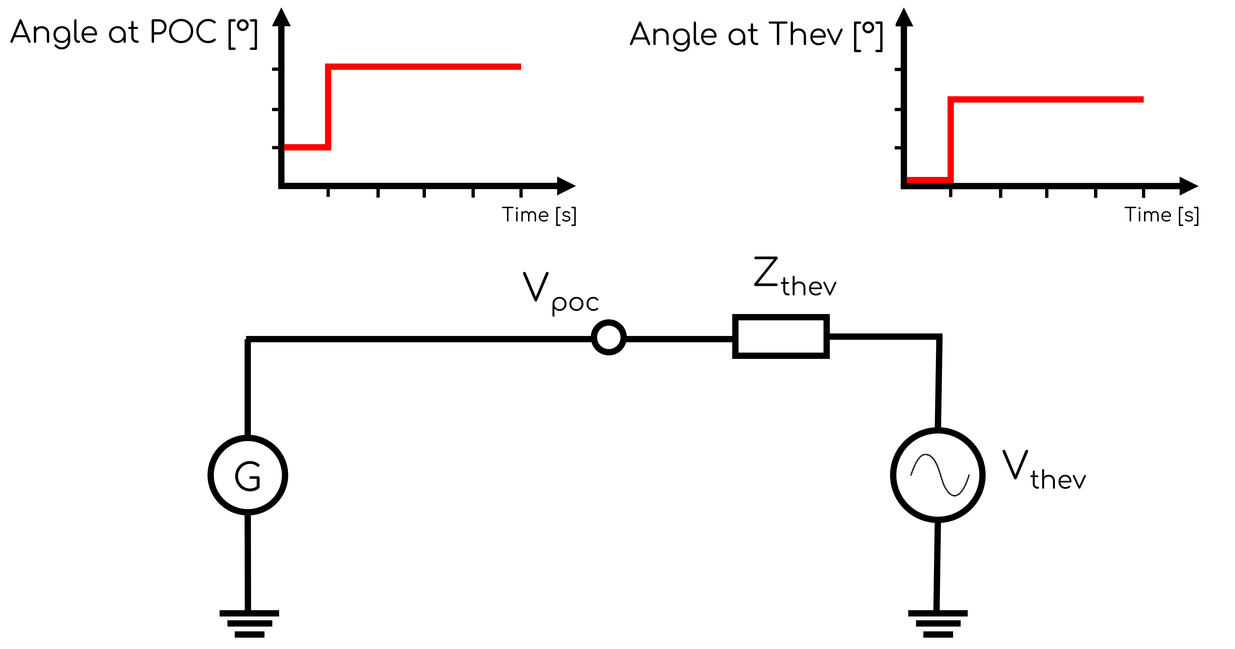
The purpose of I-5.2.1 is to confirm your generating system's ability to ride-through phase angle changes.
- It is unclear whether the +25° and -25° angle changes should be in one test or two tests. The table implies one test, but the disturbance description implies two tests. We have assumed that the table is incorrect and two tests are required.
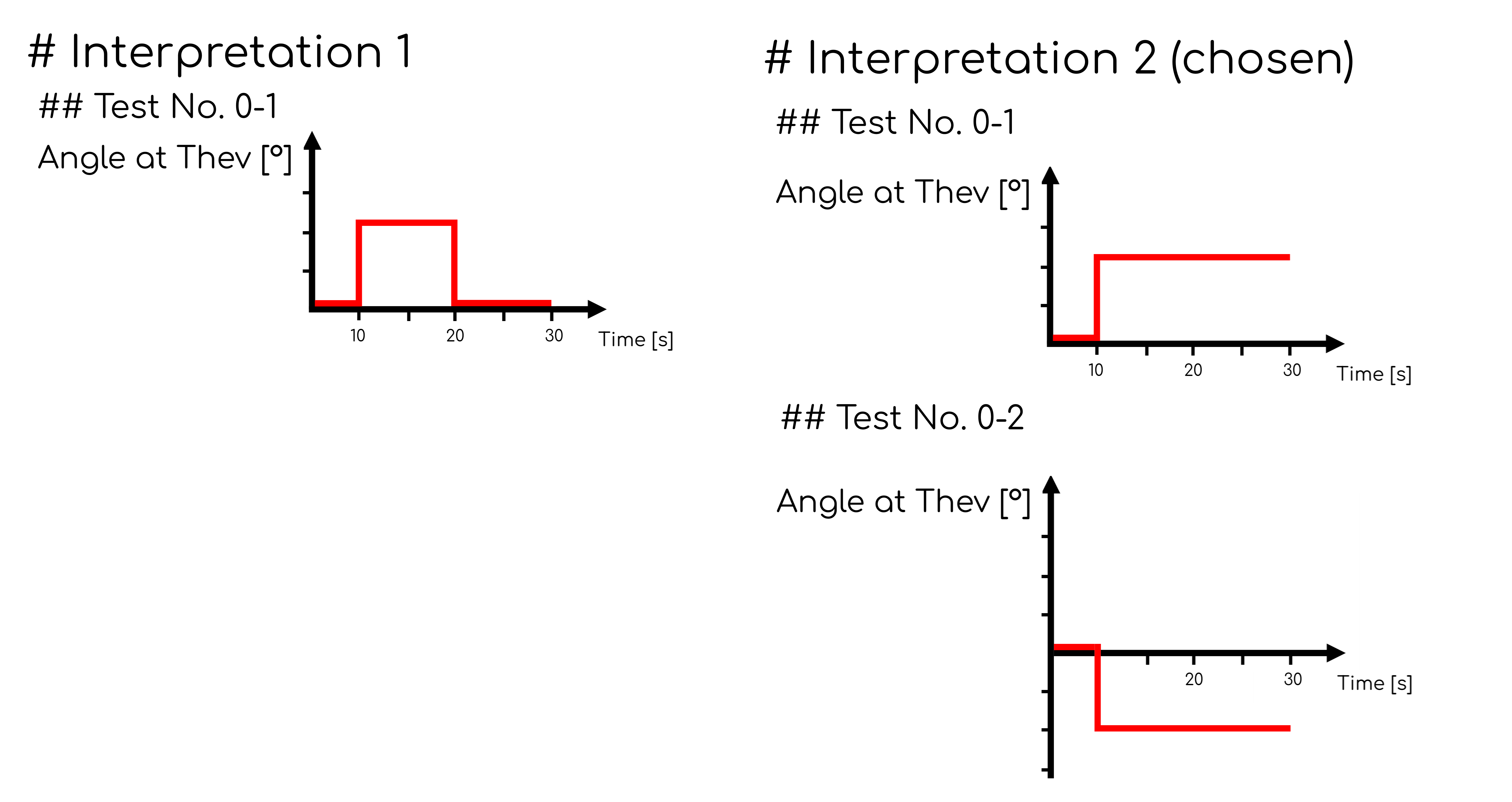
- We assumed that the voltage phase angle change was performed by controlling the Thevenin equivalent voltage source (i.e. angle playback). Note that all SMIB studies assume the reference angle is the Thevenin equivalent voltage source which therefore has an initial phase angle of 0°. Therefore, the initial phase angle at the connection point will be non-zero, depending on the initial operating condition (i.e. Vpoc, SCR), and will change ±25° relatively.
- "An acceptable damping ratio is 0.3 or greater [5]" is unclear. The reference to IEEE2800 clarifies the definition of damping ratio, but does not reference for which channels the requirement applies. We are unable to make an educated guess on which signals this damping ratio should be applied. Therefore, we have not applied this damping ratio calculation in this test.
Sources
- MISO | BPM-015 Business Practices Manual - Generator Interconnection | Version 32 | 15 December 2025
- IEEE Std 2800™-2022
Revision history
Version 1 | 26 April 2026
- First release.