Template: ENA Engineering Recommendation G99
Template version: v3
Country:

UK
Software required:
Source: ENA | Engineering Recommendation G99 | Issue 1 – Amendment 10 | 4 March 2024

Background
The number and complexity of generation interconnections have increased during the energy transition. In an effort to ensure the adequate performance of generating systems and to ensure efficient design principles by utilising standards where possible, the Energy Networks Association (ENA) published Engineering Recommendation (EREC) G99. This document is "to provide requirements for the connection of Power Generating Facilities to the Distribution Networks of licensed Distribution Network Operators (DNOs)". This template includes a selection of tests to demonstrate compliance with the required tests, collectively referred to as "G99".
Reference
Common assumptions
- The template has primarily been configured for Type C and Type D asynchronous generating systems. When required to provide a default, we have assumed the largest and highest voltage Type D generating system.
- Section 13 outlines the technical requirements for Type C and Type D generating systems. Annex C.7 outlines the simulation studies required to demonstrate compliance with Section 13. However, there are several instances where Annex C.7 doesn't include sufficient tests demonstrate this compliance or there is not a one to one relationship between these sections. We have therefore included additional tests beyond those listed in Annex C.7 and chosen to structure the template based on Section 13 and its headings rather than Annex C.7 and its headings. This decision was made since Section 13 is understood to be the section to take precedent.
13.1 Power generating module performance and control requirements
The purpose of 13.1 is to demonstrate a selection of your generating system's performance and control requirements.
- 13.1.2: This requirement doesn't make reference to the reactive power operating conditions when this is required. For tests of the P(Q) capability of the generating system see section 13.5.
- 13.1.4: Settling time is assumed as the time to achieve 95% of the change in the desired output of the Power Park Module.
- 13.1.6: This template doesn't currently include network static studies.
13.2 Frequency response
The purpose of 13.2 is to confirm your generating system's active power response to power system frequency changes.
- Frequency 'steps' in tests never exceed 1 Hz/s in accordance with 13.2.2, except for C.7.6.6 (see note below).
- 13.2.4.1(c): "As much as possible of the proportional reduction in Active Power output" is assumed to mean 95% of the expected change in active power.
- 13.2.4.1(c) & 13.2.5.1(b): "...initiating a power frequency response" is assumed to mean the time to achieve 10% of the expected change in active power.
- 13.2.5.1(b): There is no 10 second settling time requirement for LFSM-U tests like there is for LFSM-O (i.e. 13.2.4.1(c)). However for simplicity in the test configuration, we also check for 10 second settling time for under frequency ramps.
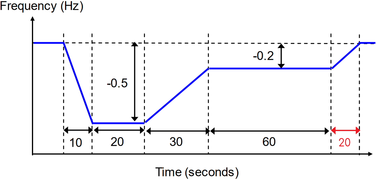
- C.7.6.6: The test methodology in Figure C.8.1 shows a frequency ramp rate of 2 Hz/s which exceeds the maximum required ramp rate as outlined in 13.2.2. Nevertheless the 2 Hz/s ramp rate was included in the test. Additionally, we couldn't find a difference between the test methodologies of BC1 and BC3. Therefore BC3 test has been disabled by default.
- C.7.7.2: "a sufficiently large reduction in the measured system frequency" was assumed to be 47.5 Hz.
- 13.2.6: By default, generating systems will be set to operate in LFSM, not FSM. Therefore, FSM requirements are not enabled by default.
- 13.2.6.4(c): "Maximum admissible initial delay t1" is assumed to mean the time to achieve 10% of the expected change in active power. "Activation time t2" is assumed to mean the time to achieve 95% of the expected change in active power.
Our template doesn't currently include the load rejection test following the methodology outlined in C.7.6.2 - C.7.6.5.
13.3 Fault ride through
The purpose of 13.3 is to confirm your generating system's response during and after disturbances.
Step 1 - Choose the % retained voltage
In accordance with Table C.7.1, select the relevant retained voltage % in Loop: Start Nodes 1056, 1068, 1075 in accordance with the following:
- Connection point voltage < 110 kV: 10% retained voltage.
- [Default] Connection point voltage ≥ 110 kV: 0% retained voltage.
- C.7.5.3: The statement, "The simulation study should be completed with the Power Generating Module operating at...the fault level at the Connection Point at minimum as notified by the DNO...A minimum short circuit power of 50 MVA is a generic minimum fault level that should be assumed" is unclear. We have assumed the study be completed at minimum SCR.
- C.7.5.2: The extended voltage recovery tests are not explicitly required in C.7.5.2. Nevertheless, additional tests have been included to cover the requirements of section 13.3.1.1. This extended voltage recovery is created through a combination of two events. This methodology helps to avoid using a Thévenin equivalent voltage source playback for very low voltage dips which has been known to cause unrealistic and undesirable generating systems responses. The two events are:
- A fault impedance applied at 5 seconds for a duration of 140ms.
- A Thévenin equivalent voltage source playback ramp at from 5.141 seconds onwards.
- 13.3.1.11(c): "Where necessary, on reasonable request the DNO will specify the pre-fault and post fault short circuit capacity (in MVA) at the Connection Point". Our test configuration doesn't currently include an SCR change during the simulation.
13.4 Voltage limits and control
The purpose of 13.4 is to confirm the capability of your generating system's reactive power control system.
Step 1 - Choose sufficient Thévenin equivalent voltage source step sizes
Choose step sizes for the following:
- C.7.4.2 (i): Choose a Thévenin equivalent voltage source step size which is "sufficiently large...to cause a change in Reactive Power from zero to the maximum lagging value at Registered Capacity." The default value is -0.10 [p.u.].
- C.7.4.2 (ii): Choose a Thévenin equivalent voltage source step size which is "sufficiently large...to cause a change in Reactive Power from zero to the maximum leading value at Registered Capacity." The default value is +0.10 [p.u.].
- 13.4.4.2: This clause outlines that the generating system must meet the requirements outlined in Annex C.5. Therefore, many Analysis Nodes reference clauses within Annex C.5.
- C.5.4.1(i): Commencement time is assumed as the time to achieve 10% of the change in the Reactive Power output of the Power Park Module.
- C.5.4.1(ii) - First dot point: We have not provided simulations to show the generating system meets the 2 second requirement.
- The voltage changes are created by modifying the Thévenin equivalent voltage source via playback. This methodology typically provides a sufficient response for small voltage changes. If the test methodology is expanded to larger voltage changes, we recommend using the
VDISTURBANCECommand instead.
13.5 Reactive capability
The purpose of 13.5 is to confirm your generating system's reactive power capability while operating across a range of different conditions (e.g. active power outputs and connection point voltages).
Step 1 - Choose static study or dynamic study methodology
We have provided two alternate methodologies:
- [Default] Methodology 1 - Static studies: C.7.3.2 and C.7.3.3 outline the requirement for "load flow simulation studies to demonstrate operation at points A, B, E and F" and therefore this methodology is provided by default.
- Methodology 2 - Dynamic studies: Using static studies in methodology 1 to confirm capability may have limitations for some OEM models. This would occur in situations where there are configuration/performance details which are present in the dynamic model representation of the generating units and Power Park Module, but not in the respective static model representation.
Step 2 - Configure Vpoc for operating points B and F
Configure the Loop: Start Nodes 1026 and 1017 based on the requirements for operating points B and F:
- [Default] C.7.3.2 - Connection point voltage > 33 kV:
- Point B: Vpoc = 0.97 [p.u.]
- Point F: Vpoc = 1.03 [p.u.]
- C.7.3.2 - Connection point voltage ≤ 33 kV:
- Point B: Vpoc = 1.00 [p.u.]
- Point F: Vpoc = 1.00 [p.u.]
- Tests are conducted at infinite SCR.
- Dynamic study tests are conducted using a playback generator with infinite inertia.
- 13.5.6: We have included a Constrained Ppoc(Qpoc) capability curve to demonstrate performance with 13.5.6. By default, this capability curve is only shown for Vpoc = 1.0 [p.u.] since voltage dependence on Ppoc and Qpoc capability is already explored in 13.5.4 and 13.5.5.
13.6 Fast fault current injection
The purpose of 13.6 is to demonstrate your generating system's fault ride-through performance.
- 13.6 doesn't provide requirements for over voltage ride-through performance and therefore such tests have not been included by default. However, the tests assessing under voltage ride-through performance and transition bands can be extended to over voltages, if required.
- 13.6.2: Under voltage disturbances of 0% retained voltage (i.e. bolted faults) haven't been included since this section describes "...Transmission System faults which...will be seen in the Distribution Network as a voltage depression". It is not possible to get such low retained voltages for transmission system faults.
- 13.6.2(b): Commencement time is assumed as the time to achieve 10% of the change in the reactive current output of the Power Park Module. Settling time is assumed as the time to achieve 95% of the change in the reactive current output of the Power Park Module.
- 13.6.2(b): We have assumed that the statement, "Figure 13.15 defines the reactive current IR that is to be supplied during a fault on the transmission System and which is dependent on the pre-fault operating conditions, and the voltage retained at the Connection Point" implies that the tests should be conducted at the pre-fault operating conditions of Qmin, Q0 and Qmax.
- 13.6.2(e): We haven't included tests to demonstrate "smooth transition between any of its voltage, power factor, or reactive power control modes". We have included tests to demonstrate, "smooth transition between...fault ride through mode in order to prevent the risk of instability which could arise in the transition between the steady state voltage operating range and abnormal conditions where the retained voltage falls below 0.90 pu of nominal voltage."
13.7 Black start capability and rapid re-synchronisation
The purpose of 13.7 is to confirm that your generating system's black start capability.
We don't currently provide tests for 13.7.
13.8 Technical requirements for embedded medium power stations
Section 13.8 references additional requirements in the Grid Code which may be relevant to the Generator.
We don't currently provide tests for 13.8. If required, the tests may need to complete the requirements as outlined in C.7.2.
13.9 Operational monitoring
The purpose of 13.9 is to confirm that your generating system has adequate communications equipment.
We don't currently provide tests for 13.9.
13.10 Steady state load Inaccuracies
The purpose of 13.10 is to confirm that your generating system has an adequate standard deviation of load error.
We don't currently provide tests for 13.10.
C.7.8 Model verification and validation
The purpose of C.7.8 is to demonstrate that the "models supplied to the DNO under the DDRC are fit for purpose." We have provided the tests as outlined in this section. However, you may want to provide further tests to demonstrate compliance, such as those provided in the Model setup template.
- C.7.8.2: We assumed that the last frequency ramp is 0.1 Hz/s, which is the same ramp rate as the ramp from 49.5 Hz to 49.8 Hz.
Sources
- ENA | Engineering Recommendation G99 | Issue 1 – Amendment 10 | 4 March 2024
- ENA | Distributed Generation Connection Guide: G98 & G99 | Version 1.0 | March 2024
- ESO | Grid Code | Issue 6 - Revision 26 | 5 September 2024
Revision history
Version 3 | 12 December 2025
Improvements- Added Action Nodes.
- 13.3 Fault ride through - Extended voltage recovery: Added missing applied test subplot in Plot Node
1080.
Version 2 (v1.4.19) | 27 November 2024
- Removed extra blank subplot (was present in only some Plot Nodes).
- Fixed template mapping issue which caused LVRT and HVRT signals to not appear on the specified sub-plots.
Version 1 (v1.4.18) | 15 November 2024
- First release.