Template: NGESO System Oscillation Assessment of Inverter Based Resources (IBRs)

Template version: v2
Country:

UK
Software required:
Source: System Oscillation Assessment of Inverter Based Resources (IBRs) - Modelling instruction for PSS/E and PSCAD models (v1.0, 31 Jan 2024)

Background
This gridmo template:
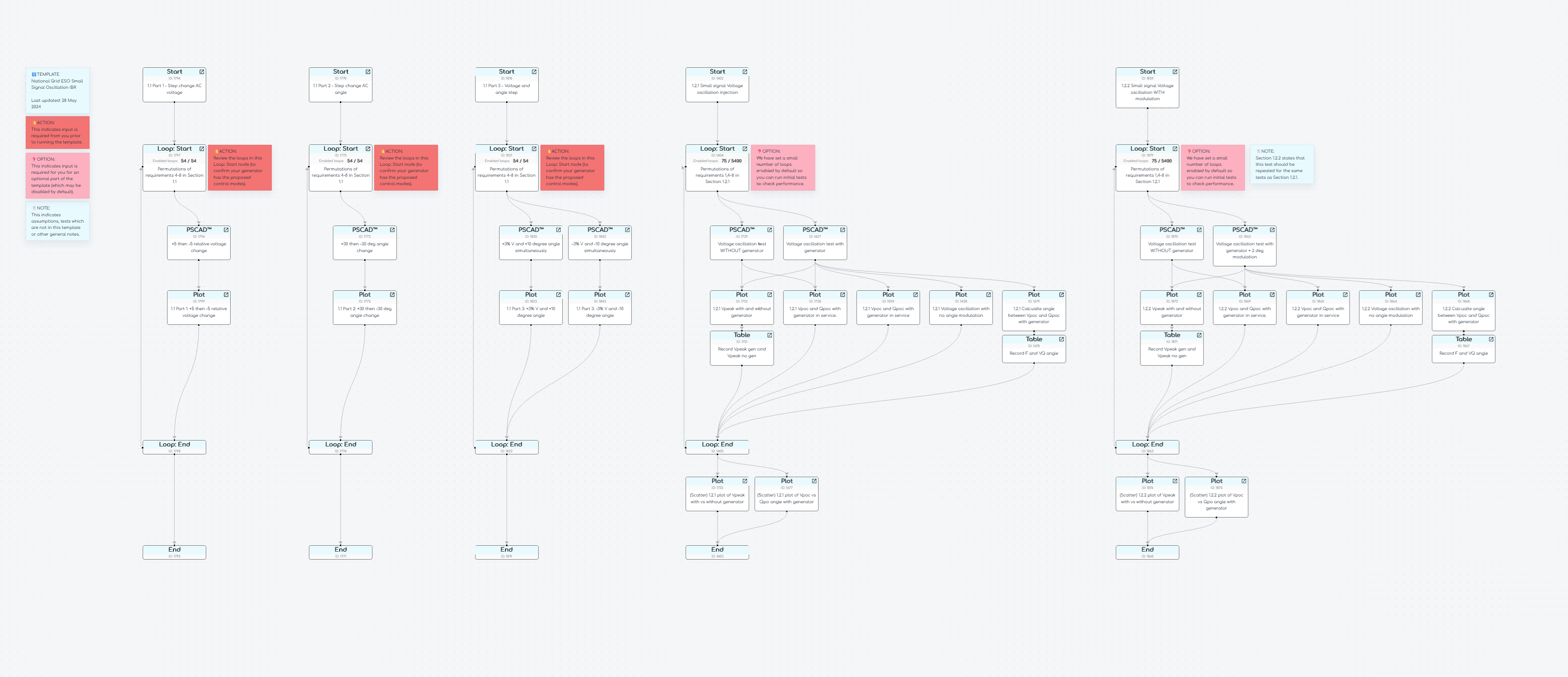
- Implements Section 1.1 and Section 1.2.1 of National Grid ESO's System Oscillation Assessment of Inverter Based Resources (IBRs) requirements.
This template does not yet include Section 1.2.2, Section 1.3 (Active frequency scan) or Section 1.4 (Eigenvalue method).
National Grid ESO's System Oscillation Assessment of Inverter Based Resources (IBRs) requires a very large number of PSCAD™ studies given the large number of permutations of system strength, control modes, initial active power and initial reactive power.
This template by default has a large number of loops initially disabled - so you can get first pass results quickly when starting with this template.
Configuration
To use this template:
- Configure your Global Variables using gridmo's Model setup template.
- Add this template to your flow by using the
Add Flowbutton, or alternatively using the download button above. If downloaded using the above button, you will need to transfer your general data, global variables and scenario variables. - If your generating system cannot operate in voltage droop control, Q control or PF control - review all
Loop StartNodes in the template and disable the rows which require the control modes that your system does not support.
Assumptions
- We assume that these studies only need to be completed in PSCAD™ (e.g. no PowerFactory EMT studies are required).
- Section 1.1 (Step Change - EMT Simulations):
- The ±5% step change in AC grid voltage are completed in the same test, with an relative voltage change to +5% to -5% separated by 10 seconds per step.
- The ±30-degree phase jump in AC voltage angle are completed in the same PSCAD™ simulation, with an angle change to -30 degrees and then +30 degrees separated by 15 seconds.
- For the ±3% step change in AC grid Voltage combined with ±10-degree phase, only 2 permutations are included (i.e. +3% voltage and +10-degree phase OR -3% voltage and -10-degree phase).
- Section 1.2 (Small Signal Injection Study):
- There are a very large number of PSCAD studies required in this test (over 5,000) based on the permutations the frequency range of 1-100 Hz at 1 Hz resolution with all required initial active power, reactive power and reactive power control modes. By default, we have limited the enabled loops to those in the frequency range of 1-25 Hz, at minimum system strength only, at 50% active power and 0% reactive power. This is so you can get first pass results quicker.
- We have not included Section 1.2.2 (tests to apply a ±2 phase oscillation), as this would add another 5,000 PSCAD™ studies to the template. However, gridmo does support phase oscillation - see the
VOLT_OSCILcommand'sPSOMAG=optional argument here.
Sources
Revision history
Version 2 (v1.4.19) | 27 November 2024
- Removed incorrect maunal y-axis scaling values in Plot Node
1728. - Removed unused second row in Plot Node
1732.
Version 1 (v1.4.16) | 30 July 2024
- First release of template.