Template: AEMO Voluntary Specification for Grid-forming Inverters: Core Requirements Test Framework

Template version: v1
Country:

AU
Software required:
Source: AEMO | Voluntary Specification for Grid-forming Inverters: Core Requirements Test Framework | January 2024

Actions
- Configure your Global Variables and Scenario Variables using gridmo's Model setup template.
- Ensure that smiby v22 (or greater) has been added to your project's PSCAD™ model. See the smiby page for more details.
- Add this template to your project.
Background
AEMO's Voluntary Specification for Grid-forming Inverters (May 2023) specifies the 'core' technical capabilities for power-electronic devices to be classified as grid-forming inverters (GFMI). The specifications are categorised into 6 capabilities of GFMI as follows:
- Voltage Source Behaviour
- Frequency Domain Response
- Inertial Response
- Surviving the Last Synchronous Connection
- Weak Grid Operation and System Strength Support
- Oscillation Damping
A set of simulation tests to guide the assessment of these specifications is provided in AEMO's Core Requirements Test Framework. The framework provides the following 7 simulation tests which aim to demonstrate the 6 core capabilities in simulation:
- Loss of synchronous machine - discharging
- Loss of synchronous machine - charging
- Loss of synchronous machine - limits
- Loss of synchronous machine - power balance
- RoCoF up and down
- SCR ramp down with fault
- Angle step change
Reference
Tests 1-4 - Loss of synchronous machine
This template does not currently include the loss of synchronous machine tests (Tests 1-4). They require a template-specific custom testbench consisting of duplicating your generating system (Simplified Network With Load (SNWL) testbench). The gridmo team can assist with setting this up, if required for your project.
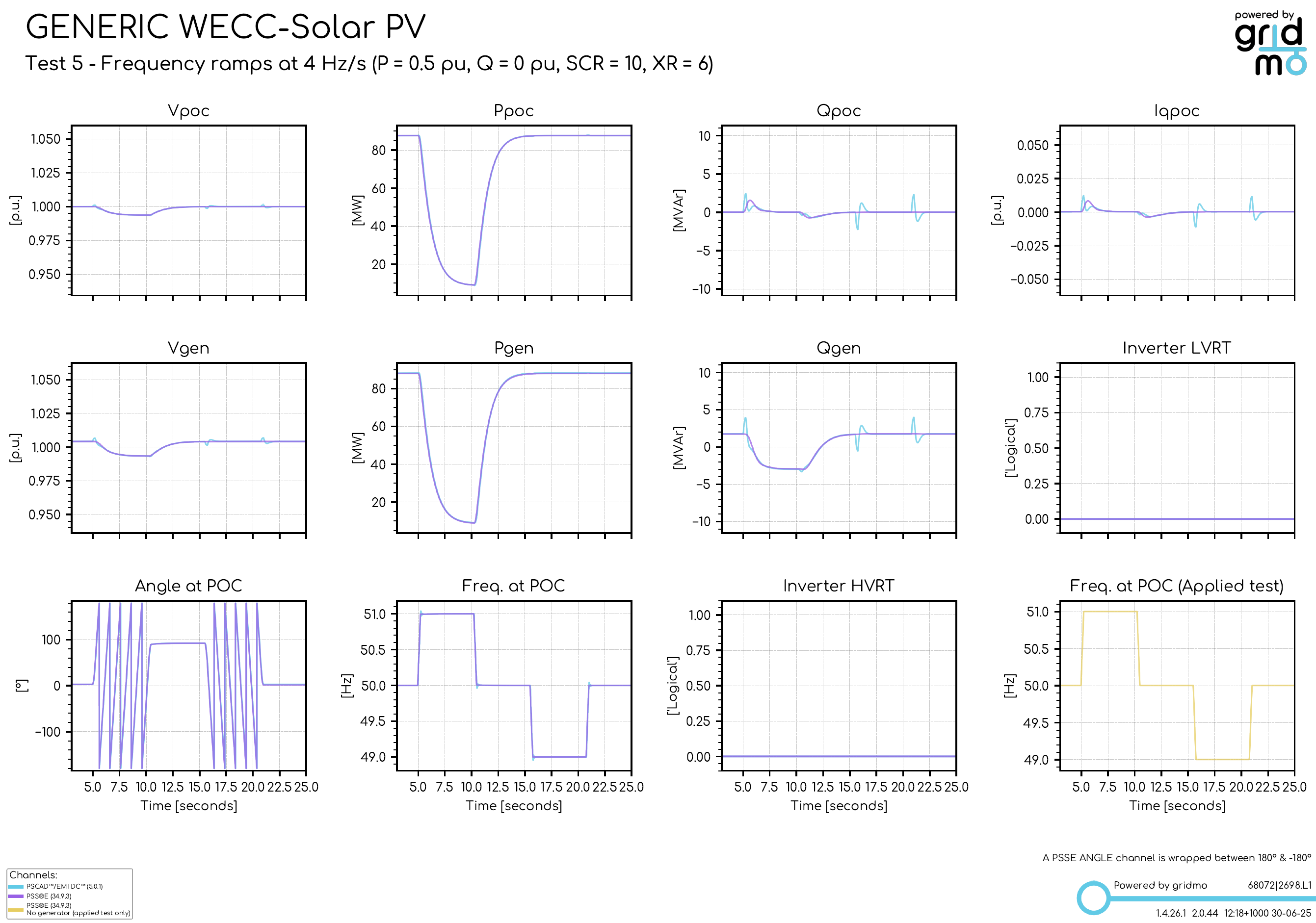
Test 5 - RoCoF up and down
The purpose of this test is to assess the stability of the GFM plant in response to changing frequency.
Test 6 - SCR step down with fault
The purpose of this test is to assess the stability of the GFM plant down to a minimum SCR level of 1.25.
PSS®E may be very unstable at an SCR of 1.25 for some models, so we have assumed that this is a PSCAD™ only test. However, a pre-configured (but disabled by default) PSS®E test is included.
Test 7 - Angle step change
The purpose of this test is to assess the GFM plant's active power response time and magnitude to angle step changes.
- To test success criteria a), we have assumed that the 'peak active power change' is the maximum value reached by the active power at the POC, after the 10 degree angle step change. This check is provided in Analysis Node
2725. - To test success criteria b), we have assumed that the 'response time to 90% of initial change in instantaneous active power' is the rise time from 0% to 90% of the maximum value reached by the active power at the POC, after the 10 degree angle step change. This check is provided in Analysis Node
2725.
Sources
- AEMO | Voluntary Specification for Grid-forming Inverters: Core Requirements Test Framework | January 2024
- AEMO | Voluntary Specification for Grid-forming Inverters | May 2023
Revision history
Version 1 | 13 August 2025
- First release.