Template: AEMO System Strength Impact Assessment Guidelines (Appendix B)

Template version: v6
Country:

AU
Software required:
Source: AEMO | System Strength Impact Assessment Guidelines | Version 2.2 | 1 July 2024

Before running this template, complete the following:
- Configure your Global Variables and Scenario Variables using gridmo's Model setup template.
- Add this template to your project.
- Configure the additional Global Variables marked as '[Unique to AEMO SSIAG template]' (e.g.
$ssiag_fault_duration_1changes depending on your nominal connection point voltage). - If your X/R ratio at the connection point is unknown, for each
Loop StartNode, disable all loop rows, then only enable those withX/R=3orX/R=10rows. - Set
$ssiag_withstand_scrto your target Withstand SCR for your generating system.
Background
Inverter based generators and loads can impact the grid in ways which require network infrastructure upgrades. AEMO introduced the System Strength Impact Assessment Guidelines (SSIAG) to quantify these impacts for individual projects by assessing a plant’s capability to ride through low SCR operating conditions. The calculated Withstand SCR value is then used by NSPs to calculate project-specific network service charges, whereby projects will be charged more if the NSP must provide for a higher SCR for the plant to operate satisfactorily.
AEMO published a methodology used to quantify these impacts in Appendix B of the following document: AEMO | System Strength Impact Assessment Guidelines | Version 2.2 | 1 July 2024. For clarity, as of the time of writing this template, this document is the latest document in force under the National Electricity Rules.
However, AEMO has since published an updated methodology in the following document: - AEMO | System Strength Impact Assessment Guideline Withstand SCR Methodology Review | Version 2.1 | 28 February 2025. This new document has not officially been adopted under the NER but AEMO, "...encourages NSPs to consider adopting the principles of the methodology proposed in the technical note...". Given the likelihood of this new methodology being officially adopted and NSPs adopting this in the interim, we have updated our SSIAG template in accordance with this new methodology in Section 5 of the Technical Note.
As stated by AEMO, "It should be noted that this proposal reflects AEMO's current thinking for further consultation and is not an amendment to the SSIAG". If you would like a copy of the old SSIAG methodology, please contact us.
Whilst the SSIAG document explains what is required as demonstration of the Withstand SCR, there is no clear guidance provided on how to identify the Withstand SCR for a particular project.
If, based on your engineering judgement, a given generating system successfully rides through these tests for a given SCR, it does not confirm that it is stable under all modes for this SCR. However this may help early stage projects identify the likely range for the plant's withstand SCR.
Additional studies will likely be required to confirm this SCR is stable for your generating system, such as the AEMO Generator Performance Standards (GPS) template.
Configuration
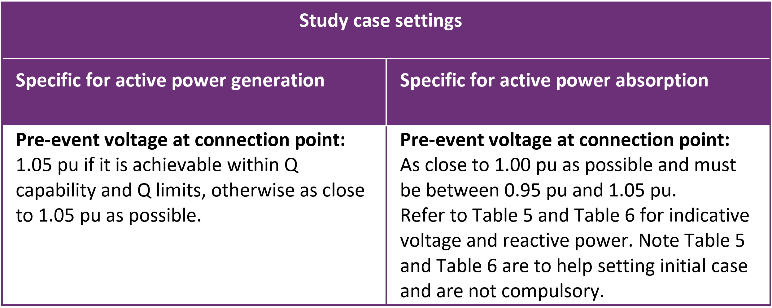
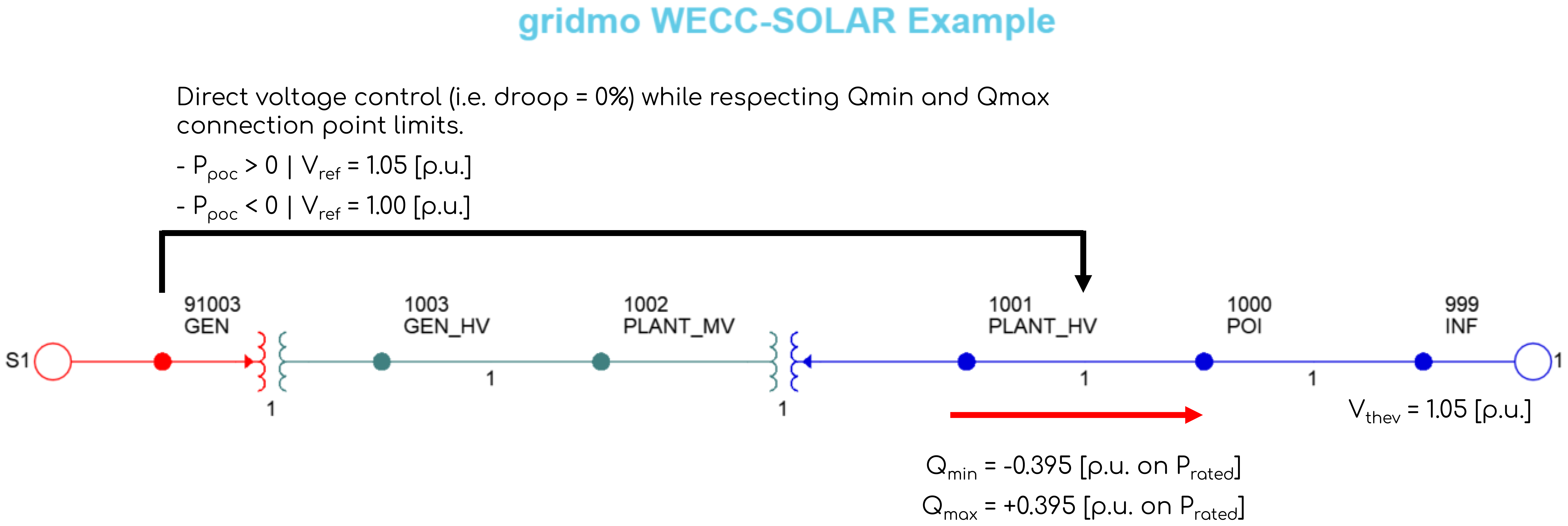
The pre-event operating conditions required in the Appendix B tests require particular configuration. These conditions are described in the image below.

The image below shows the static configuration required to achieve this initial operating condition. Note that we use the PSS®E Static Node to achieve this operating point. To achieve this using PSCAD™ Nodes only would require custom static solver logic in PSCAD™. Therefore, we strongly recommend having a PSS®E Static case, even if this model is a heavily simplified representation of the generating system.

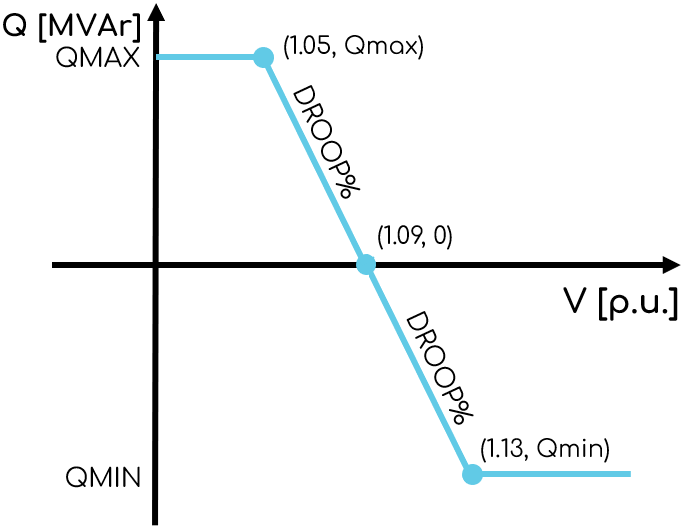
Note that for many projects operating, this operating condition may not be realistic. Consider the example below, where Qpoc = Qmax = +0.395 [p.u. on Prated] to achieve Vpoc = 1.05 [p.u.]. For a generating system operating with a 4% droop curve, this would imply that Vref is 1.09 [p.u], as shown below. Nevertheless, due to the explicit description from AEMO, the template has adopted this operating condition.

Helper 1 - Coarse search for Withstand SCR
Demonstration of adequate performance for all tests in Appendix B is used to indicate the likely Withstand SCR of your generating system. However, when starting this process it can be useful to run a smaller subset of tests across a large range of SCR values to coarsely understand where the plant may begin to have stability issues.
The Withstand SCR helper has been provided to help you complete this coarse assessment of Withstand SCR prior to running all of the Appendix B tests.
By default, the helper is configured to work for positive active powers. For BESS, the l_pcmd Loop Variable can be updated for the charging scenario to ensure the active power command is reduced according to Table 1 of the Technical Note.
Section 7.4.4(p)
The purpose of Section 7.4.4(p) is to demonstrate your model's ability to run a flat run in a robust manner.
Appendix B - Table 2
The purpose of Table 2 is to demonstrate your model's ability to ride through faults under very low grid SCR conditions.
The test duration is assumed to be 15 seconds. Figures 12, 13 and 14 in the Technical Note show simulations running for 10 seconds after the application of the disturbance.
Appendix B - Table 3
The purpose of Table 3 is to demonstrate your model's ability to ride through grid voltage disturbances under very low grid SCR conditions.
Appendix B - Table 4
The purpose of Table 4 is to demonstrate your model's ability to ride through sudden changes in grid SCR conditions due to network events (e.g. a line tripping).
Assumptions
- This template helps with Appendix B studies but doesn't cover all SSIAG requirements like calculating '∆AFL' at the connection point.
- The SSIAG is unclear if both PSS®E and PSCAD™ should be overlaid for the first two tables of tests in Appendix B. It is also unclear if error bands in compliance with AEMO's PSMG are also required. Both have been included for completeness.
- The SSIAG does not state what generator output channels should be presented as part of Appendix B. We have used the same plot structure as our AEMO DMAT template.
- PSS®E does not natively support
3PHGfaults. Hence for this template, we apply3PHfaults in PSS®E and3PHGfaults in PSCAD™.
Sources
- AEMO | System Strength Impact Assessment Guideline Withstand SCR Methodology Review | Version 2.1 | 28 February 2025
- AEMO | System Strength Impact Assessment Guidelines | Version 2.2 | 1 July 2024
- AEMO | System Strength - System strength in the NEM explained | Version 1.0 | 23 March 2020
Revision history
Version 6 | 12 October 2025
Improvements- Updated template to use Action Nodes.
- Updated Global Variable, "ssiag_fault_duration_1" description from "Vn = 275 kV or Vn = 330 kV | Fault duration = 80 ms" to "Vn = 275 kV or Vn = 330 kV | Fault duration = 100 ms".
Version 5 | 3 April 2025
New- Updated tests based on AEMO's System Strength Impact Assessment Guideline Withstand SCR Methodology Review.
- Updated helper run fault duration to 120ms.
- The test duration for Table 2 tests was reduced from 21 seconds to 15 seconds.
- Section 7.4.4(p): The chosen flat run simulation time was updated from 45s to 35 to represent a "...a stable simulation initialisation run > 30 s".
Version 4 | 17 October 2024
- Updated to AEMO SSIAG v2.2 (1 July 2024) - note there were no changes to the tests required (Section 7.4.4 and Appendix B were not updated in this revision). Removed SSIAG version number from plot subtitles.
Version 3 | 9 April 2024
- Updated to new template structure, standardised template sticky notes.
- Added
low.scr.mode=yesto allPSS®E StaticNodes to improve low SCR convergence performance. - Expanded helper run to loop down to SCR of 1.2 (was previously minimum of 2.0).
- Added additional Advanced Parameters to the helper run to help with low SCR convergence.
- Disabled POC X/R 3 and X/R 10 tests by default in all
Loop Startnodes.
Version 2 | 30 January 2024
- Fixed plot sub-titles overlapping customer logos when describing SCR and XR in some
PlotNodes.
Version 1 | 1 August 2023
- First release.