Template: Dynamics Working Group Procedure Manual - Dynamic Model Quality Test Guideline
Template version: v6
NEW!Country:

US
Software required:
Source: ERCOT | Dynamics Working Group Procedure Manual | Revision 24 | 5 June 2025

How to add this template to your project
- From within your gridmo project, open the flow dropdown and select 'Add flow'.
- Select the template you want to use and click 'Add to project'.

Background
The Dynamics Working Group (DWG) is a working group consisting of representatives from ERCOT, Transmission Service Providers (TSPs), Texas Reliability Entity (Texas RE), and Public Utility Commission of Texas (PUCT). This procedure manual includes dynamic model requirements such that the DWG can effectively and accurately simulate dynamic and transient events in the ERCOT System. These dynamic models and model testing shall be submitted to ERCOT and the relevant TSP as part of the interconnection process.
As outlined in section 3.1.5 of the DWG procedure manual, the model tests depend on the plant technology and models. The "list of applicable tests" table has been split into two tables for clearer understanding of the requirements:
| Technology type | PSS®E model type | PSS®E generic model | PSS®E user defined model | PSCAD™ | TSAT |
|---|---|---|---|---|---|
| Synchronous machines | Generic model | ✅ | |||
| Synchronous machines | User defined model | ✅ | ✅ | ✅ | |
| Non-Synchronous machines | Generic model | ✅ | ✅ | ||
| Non-Synchronous machines | User defined model | ✅ | ✅ | ✅ |
This template is configured such that the user can run and overlay all three software results, if required. Note that the template is configured such that you would not be required to submit PSS®E generic and PSS®E user defined model results.
| Test | Synchronous machines | IBRs, WGRs, and IBTEs | AGS-ESR |
|---|---|---|---|
| 3.1.5.2 Flat start test | ✅ | ✅ | ✅ |
| 3.1.5.3 Small voltage disturbance test | ✅ | ✅ | |
| 3.1.5.4 LVRT test | ✅ | ✅ | |
| 3.1.5.5 HVRT test | ✅ | ✅ | |
| 3.1.5.6 Large voltage disturbance test | ✅ | ||
| 3.1.5.7 Small frequency disturbance test | ✅ | ✅ | |
| 3.1.5.8 System strength test | ✅ | ||
| 3.1.5.9 Phase angle jump test | ✅ | ||
| 3.1.5.11 Small voltage disturbance test | ✅ | ||
| 3.1.5.12 Frequency change and inertia response test | ✅ | ||
| 3.1.5.13 System strength test | ✅ | ||
| 3.1.5.14 Phase angle jump test | ✅ | ||
| 3.1.5.15 Loss of synchronous machine test | ✅ | ||
| AVR test | ✅ | ✅ | ✅ |
| PFR test | ✅ | ✅ | ✅ |
As outlined in [3] and [4], ERCOT has recommended to check AVR/PFR performance while checking MQT. These optional tests have therefore been included.
Several existing tools exist to complete such tests (e.g. DMView for PSS®E tests, PMView for PSCAD™ tests and the "TSAT Model Quality Test (MQT) Case Preparation tool" for TSAT tests). This template in the gridmo software platform is a commercial solution which allows engineers to:
- Launch all software in one click and have all software run in parallel.
- Overlay results automatically.
- Review results automatically.
- Overlay MQT results for old and new models for operational resources.
- Launch simulations without editing configuration files or completing environment management.
- Access advanced debugging to troubleshoot issues.
- Contact a team of electrical engineers for questions and support.
- And more!
To learn more about gridmo, please visit our website here: https://www.gridmo.io/.
Reference
Common assumptions
- (Section 3.1.6.3) - Sub-synchronous tests are not yet included in this template, though the VQ oscillation tests as part of the AEMO DMAT template could be modified for this purpose.
- Section 3.1.5.1: "Unless the test requires otherwise", the default initialization conditions are:
- Ppoi = 1 [p.u.]
- Qpoi = 0 [p.u.]
- Vpoi = 1 [p.u.]
- Thevenin equivalent impedance ≈ 0 [Ω] (i.e. SCR = infinite) - Note that this default assumption was made by looking at sample results provided by ERCOT and by looking at the image provided at the end of section 3.1.5.1.
- General: Supporting documentation is not included in this template. See [3] for a full list of items that you must include in a model submission package.
- Section 3.1.2: The requirement, "Where multiple models are provided (e.g. PSS/E, TSAT, PSCAD), the model response shall be consistent across software platforms to the extent of platform capability" is subjective. We have assumed the following quantitative error bands:
- Vpoc: Models must remain within an error band of ± 0.005 [p.u.] for 95% of samples after a 5 second initialization period.
- Ppoc: Models must remain within an error band of ± 1% x (Pbase) [MW] for 95% of samples after a 5 second initialization period.
- Qpoc: Models must remain within an error band of ± 1% x (Qbase) [MVAr] for 95% of samples after a 5 second initialization period.
- General: The signal profiles show a mixture of events starting just before t = 5 [s] (e.g. 3.1.5.11 and 3.1.5.12) and events starting at t = 5 [s] (e.g. 3.1.5.3, 3.1.5.7 and 3.1.5.8). To ensure consistency, simplicity when calculating metrics (e.g. response time) and sufficient time for PSCAD™ model initialization, for, we have assumed that all events start at t = 5 [s].
3.1.5.2 Flat start test
The purpose of this test is to demonstrate your model's ability to initialize and run a flat run in a robust manner.
- We assume that the flat start test is also designed to check the initialization time of the PSCAD™ model. We have assumed that the PSCAD™ model should initialize in less than 5 seconds, where the initialization time is based on a settling time calculation where the connection point active power and reactive power must settle within "±1% of their reference setpoint values" or ±1% of their base values, whichever is greater. The ±1% of base value requirement was introduced because certain operating conditions (e.g. Qpoc = 0 MVAr), "±1% of their reference setpoint values" can become a very small number (i.e. ±1% of 0 MVAr).
3.1.5.3 Small voltage disturbance test
The purpose of this test is to confirm your generating system's response during and after small voltage disturbances when operating in voltage control mode.
- We assume that the plant must be put into voltage control mode for this test, even if the default control mode is different (e.g. power factor control mode).
- We assume that the voltage dip test is conducted using a Thévenin equivalent voltage source playback.
3.1.5.4 LVRT test
The purpose of this test is to confirm your generating system's response during and after large voltage disturbances when operating in voltage control mode.
- We assume that the plant must be put into voltage control mode for this test, even if the default control mode is different (e.g. power factor control mode).
- We assume that the test is conducted using a Thévenin equivalent voltage source playback. However, for very low/high voltage changes (e.g. < 0.1 [p.u.]) this method been known to cause unrealistic and undesirable generating systems responses. If your model observes such unrealistic and undesirable generating systems responses from the very low playback model voltage dip, we recommend replacing the deepest voltage disturbances event with a 3PH bolted fault and use playback for the remaining events. We have assumed that the frequency playback is also activated and fixed to nominal frequency to address this potential stability issue.
- Voltage dip profile: The "Legacy" profile test figure starts at t = 5 [seconds]. Whereas the "Voltage dip" profile test figure starts at t = 2 [seconds]. We have assumed that the "Voltage drip" profile should also start at t = 5 [seconds] for the following reasons:
- Consistency with other test methodologies
- Allow for the initialization time of PSCAD™ models.
- Legacy profile: "Real power should recover to full output within 1.0 seconds of POI voltage recovery to 0.9 pu. A modest real power reduction (typically 5% of Pmax or less) may be acceptable to accommodate". We assume the active power recovery is the time taken to reach 95% of the pre-fault value.
- Voltage dip profile: "Real power should recover to full output within 1.0 seconds of POI voltage recovery to 1.0 pu." is unclear. Due to model numerical accuracy, it may never reach 100% of the pre-fault value. We assume the active power recovery is the time taken to reach 99% of the pre-fault value.
- Voltage drip profile: "Reactive current injection at the POI shall be observable immediately or very shortly after a non-zero voltage dip is applied." is unclear due to the terms "observable" and "very shortly after". We have therefore not included quantitative assessment.
3.1.5.5 HVRT test
The purpose of this test is to confirm your generating system's response during and after large voltage disturbances when operating in voltage control mode.
- "During the high voltage transient, the model should provide a fast dynamic response to absorb reactive power. The resource should be absorbing a significant amount of reactive power at the POI during the high voltage transient, and ideally within 0.5 seconds of the transient inception." is unclear due to the terms "significant amount". We have therefore not included quantitative assessment.
- We assume that the test is conducted using a Thévenin equivalent voltage source playback. However, for very low/high voltage changes (e.g. < 0.1 [p.u.]) this method been known to cause unrealistic and undesirable generating systems responses. We have assumed that the frequency playback is also activated and fixed to nominal frequency to address this potential stability issue.
3.1.5.6 Large voltage disturbance test
The purpose of this test is to confirm your generating system's response during and after balanced voltage disturbances.
- We assume that the "three-phase fault" is a bolted fault.
- "Any oscillations should be well damped." is unclear (i.e. no damping coefficient requirement has been provided). We have therefore not included quantitative assessment.
3.1.5.7 Small frequency disturbance test
The purpose of this test is to confirm your generating system's response during and after small frequency disturbances.
- The term "step" when describing the test is misleading. In a grid with inertia, instantaneous frequency changes are not possible. We have assumed a ROCOF of 5 [Hz/s].
3.1.5.8 System strength test
The purpose of this test is to confirm your generating system's ability to ride through a series of balanced faults and subsequent SCR changes. This test simulates faults being applied and being cleared such that the Thevenin equivalent impedance increases (e.g. SCR drops because lines are opening to clear a fault).
- The X/R ratio of the Thevenin equivalent impedance is unclear for initial conditions and throughout the test. We assume that the X/R ratio is constant throughout the test and remains as 100. This is based on the assumption that the example implies essentially zero Thevenin equivalent resistance.
3.1.5.9 Phase angle jump test
The purpose of this test is to confirm your generating system's ability to ride-through phase angle changes.
3.1.5.11 Small voltage disturbance test
The purpose of this test is to confirm your generating system's response during and after small voltage disturbances when operating in voltage control mode.
- "The instantaneous reactive power output of the plant should quickly respond to oppose the voltage step change for each of the step changes, with an initial peak reactive power change of at least 0.03 pu on the rated power base". We assume that the "rated power base" is the corner point Smax at the connection point.
- We assume the requirement, "The reactive power should not return to the pre-disturbance level within 6 cycles." refers to a requirement after all the grid voltage steps have been applied and Vpoi has returned to nominal. Additionally, "return to pre-disturbance level" is assumed to be a settling time calculation checking when a value returns to within ± 1% x (Qbase) [MVAr].
- We assume the requirement, "The response time to 90% of the initial change in instantaneous reactive power should occur within 1 cycle." is in accordance with the 0 -> 90% step response time definition as outlined in Figure 5(a) of IEEE2800.
- We assume that the maximum instantaneous reactive power output of the plant opposing the voltage step change occurs in the first 2 cycles following the step.
3.1.5.12 Frequency change and inertia response test
The purpose of this test is to confirm your generating system's inertial response.
- "The frequency and voltage should not oscillate excessively or deviate from steady-state levels for any significant amount of time." doesn't make sense. The test description doesn't mention modelling inertia in the Thevenin equivalent source. Therefore, the plant is not able to alter the grid frequency. Therefore, the frequency will "deviate from steady-state levels".
- "The frequency and voltage should not oscillate excessively or deviate from steady-state levels for any significant amount of time." is unclear due to the term "for any significant amount of time". We have therefore not included quantitative assessment.
- "Voltage should settle to a stable operating point when the frequency is not ramping" is unclear - both in terms of assessment methodology and requirement. We have assumed the following:
- Methodology: The settling time is the time at which the voltage returns to within ± 0.005 [p.u.]
- Requirement: The settling time must be less than 5 seconds after the frequency stops ramping.
- Test 5 - 6: The criteria, "[reactive power] response time is within acceptable range" is unclear - both in terms of assessment methodology and requirement. This is most likely referring to Figure 5(b) of IEEE2800 but that methodology is unclear. A quantitative assessment has not been included for the reactive response time for these tests.
- The term "step" when describing the test is misleading. In a grid with inertia, instantaneous frequency changes are not possible. We have assumed a ROCOF of 5 [Hz/s] for the non-ramping "steps".
We currently don't support the automatic calculation of the equivalent inertia constant. You will need to complete this calculation manually on the raw xlsx data output
3.1.5.13 System strength test
The purpose of this test is to confirm your generating system's ability to ride through a series of balanced faults and subsequent SCR changes. This test simulates faults being applied and being cleared such that the Thevenin equivalent impedance increases (e.g. SCR drops because lines are opening to clear a fault).
- The X/R ratio of the Thevenin equivalent impedance throughout the test is unclear. We assume that the X/R ratio is constant throughout the test and remains as 6.
3.1.5.14 Phase angle jump test
The purpose of this test is to confirm your generating system's ability to ride-through phase angle changes.
- We assume that the maximum instantaneous active power output of the plant opposing the angle step change occurs in the first 2 cycles following the step.
- We assume the requirement, "The response time to 90% of the initial change in instantaneous active power should occur within one cycle." is in accordance with the 0 -> 90% step response time definition as outlined in Figure 5(a) of IEEE2800.
3.1.5.15 Loss of synchronous machine test
We do not currently support this test.
3.1.6 Unit model validation
For unit model validation, please use our Overlay Setup template to overlay dynamic simulation results from power systems software (e.g. PSS®E, PSCAD™) with real data from Hardware-In-the-Loop (HIL) testing or on-site commissioning.
AVR test
The purpose of this test is to assess the performance of your generating system's voltage control system. As outlined in [3] and [4], ERCOT has recommended to check AVR/PFR performance while checking MQT. These optional tests have therefore been included. The primary source document is [5] ERCOT | IRR AVR testing expectations | 30 December 2020, as shown in the image below.
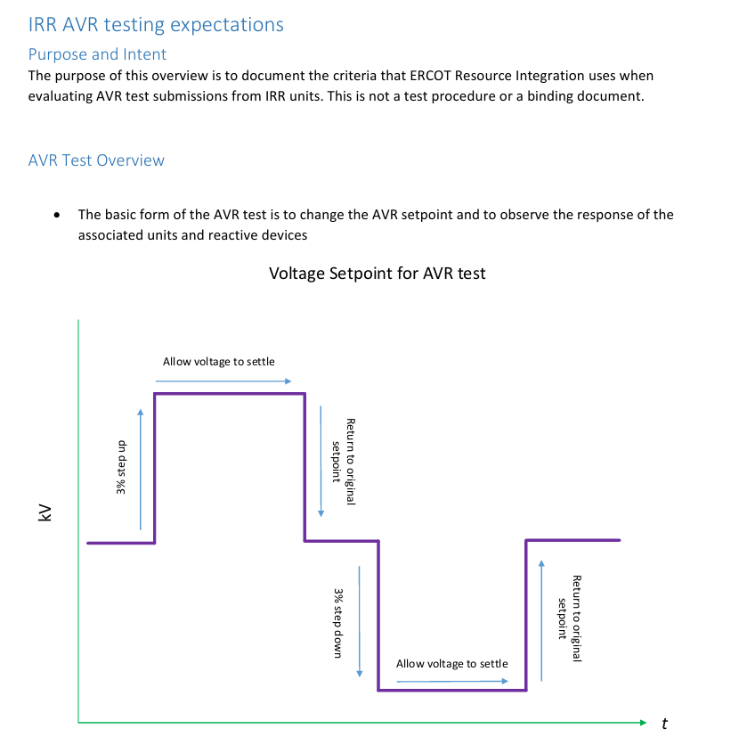
This test methodology is very similar to 3.1.5.3 and 3.1.5.11, however this test has the following main differences:
- The test is conducted at site-specific SCR.
- The test changes the plant's voltage reference setpoint (i.e. Vref) and the grid voltage remains constant.
- By default, we assume the time between Vref steps is 30 seconds and that this is the settling time requirement. This is based on the ERCOT statement, "Full dynamic response in 30 seconds or less". However, this test methodology may be varied if applicable to the plant's control system. We assume the settling time requirement is when the Qpoc values return to within ± 1% x (Qbase) [MVAr].
- We assume that the test is conducted at site-specific SCR and X/R. [4] states "Incorporate a non-zero impedance between plant model and the infinite bus testing source, for example, to establish an SCR of ~5". However, testing SCR at 5 seems arbitrary for a test which is designed to reveal site-specific issues during commissioning. We therefore recommend that this test be conducted at the site-specific SCR and X/R.
- By default, only PSS®E tests are enabled in accordance with the description in [4], which states, "Simulate the AVR/PFR tests on the PSS/e model".
PFR test
The purpose of this test is to confirm the generating system's active power response to power system frequency changes.
- We are unsure on the test methodology given [5] doesn't include information on this (see image below). Therefore, we have included a generic style of test which produces the P(f) droop characteristic.
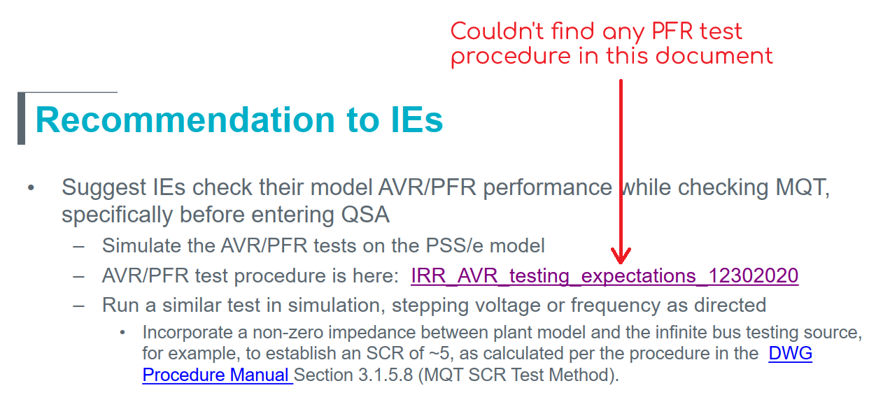
- By default, only PSS®E tests are enabled in accordance with the description in [4], which states, "Simulate the AVR/PFR tests on the PSS/e model".
Sources
- [1] ERCOT | Dynamics Working Group Procedure Manual | Revision 24 | 5 June 2025
- [2] ERCOT Nodal Operating Guides | February 1, 2026
- [3] ERCOT | Model Quality Guide - ERCOT Dynamic Model Submittal Guideline | Version 1.11 | April 2026
- [4] ERCOT | RUNNING AVR, PFR TESTS IN MQT | April 16 2025
- [5] ERCOT | IRR AVR testing expectations | 30 December 2020
- [6] IEEE Std 2800™-2022
Revision history
Version 6 | 31 May 2026
New- Added support for PSAT and TSAT.
Version 5 | 21 May 2026
New- Updated based on the latest requirements of ERCOT | Dynamics Working Group Procedure Manual | Revision 24 | 5 June 2025.
- To support the growing complexity of projects and grid codes, we created a new version of the template which fully utilizes the latest features in gridmo such as:
- Global variables in loops for easier setpoint configuration
- Multiline partial command Global Variables
- Global subplots
- Operating conditions
- PSCAD™ only initialization
From this version onwards, the legacy template library version of this template is no longer maintained.
Version 4 | 16 October 2024
Fixed- Removed
Angle at POC (Applied test)subplot from Plot Node1284(was plotting a signal which was not being exported from the connected PSCAD™ Node).
Version 3 | 29 May 2024
Fixed- Fixed typo in first loop of node
1260.
Version 2 | 15 April 2024
Improvements- Updated to align with newest template Sticky Note format.
Version 1 | 13 June 2023
- First release.