Troubleshooting
This troubleshooting guide contains warnings and errors that can occur when using gridmo as well as a list of common questions, pitfalls and tips that we have collated from our user discussions.
Checklist
Power system studies can be complex. We've put together the following checklist which provides a generic approach to troubleshooting power system studies problems.
- Logs:
- Run the simulation generating logs and standalone folders. Review the simulation summary and gridmo worker logs within the
all-tempfolder.
- Run the simulation generating logs and standalone folders. Review the simulation summary and gridmo worker logs within the
- Purpose:
- Confirm the purpose of the test. What is the purpose of the test you are completing? Are you expecting a change in P, Q or V? Are you expecting a generator to trip (or not)? What is not working as expected?
- Understand the expected performance during the test. Which, if any, of the power systems results do you expect to be correct? For example, if the test is an active power step and only one of the models is changing active power, is that model closer to being 'correct' than the other model?
- Inputs:
- Are you using the correct versions of your PSS®E models (e.g.
.savcase file,.dyrdynamics model data file and.dlluser model files if any)? - Are you using the correct versions of your PSCAD™ models (e.g.
.pswxWorkspace file,.pscxor.pslxlibrary files)? - Are you using the latest version of smiby?
- Are you applying the same Commands to both models? For example, are you applying the same SCR and X/R Commands? Are you applying the same control mode between models (e.g. fixed Q control mode, PF control mode, voltage droop control mode)?
- Are you measuring system quantities (e.g. V, P, Q) at the correct locations?
- If applicable, are you exporting values from PSS®E to PSCAD™ (e.g. tap changer position, initial conditions)?
- Are you using the correct versions of your PSS®E models (e.g.
- Use interactive visualisation plot output (HTML):
- If you double click on a sub-plot using the HTML plot output, you can zoom in/out to view all available data. Are the two models starting from the same V, P and Q set-points?
- Is there a part of the simulation when the two models misalign, such as during a fault? Check you are applying the same Command in both models.
- Use standalone folder
- Use the standalone folder to run PSS®E or PSCAD™ directly.
General
My two models don't benchmark between PSS®E and PSCAD™ (i.e. align)
Possible solutions:
- Ensure that the generator settings are the same between PSS®E and PSCAD™.
- Ensure that the transformer and cable impedances are the same between PSS®E and PSCAD™.
- Ensure the tap changer positions are the same between PSS®E and PSCAD™. If applicable, set the tap position using PSS®E Static, output from PSS®E using the
OUPTUT, VAL=TAPRATIO, TX=Command and set in PSCAD™ using theSETCommand. - Ensure the Command set-points (e.g. P, Q, PF, Vref) are set correctly at the start of the PSS®E Dynamic study, otherwise the generator may ramp to some other value.
- If using external grid playback and importing infinite bus voltage from PSS®E into PSCAD™, be careful of using absolute voltage control i.e.
0, 1.0as this will override the previously loaded infinite bus voltage. Consider using relative playback instead i.e.0, 0%.
I applied a 50% residual fault, but got a shallower fault
The SIMPLEFAULT, FZ=xx% Command calculates a fault impedance to achieve the targeted residual fault percentage with the following assumptions:
- The generator is in a SMIB model and the fault is occurring at the connection point; and
- There is no current contribution from the generator under test.
The current contribution from the generator will therefore cause the residual voltage to be slightly higher than the targeted value.
Possible solutions:
- Consider setting the SCR to near infinite (i.e.
SCR=9999) so that the generator cannot change the connection point voltage, irrespective of how much current is injected into the fault. - Consider decreasing the target residual voltage (i.e.
FZ=xx%) slightly to take into account the current contribution from the generator.
PSS®E Static
PSSEConversionError
This happens gridmo's static solver within the Engine could not satisfy all of your CONTROL Commands within the allowed simulation window.
Possible solutions:
- Ensure that
ATLINE=Arguments are orientated the correct way. In gridmo, PSS®E lines (i.e. branches) are defined to point in the direction of positive power flow.- For a generator, this means the
tobus infrom->to#idis closest the infinite bus/grid. - For a load, this means the
frombus infrom->to#idis closest to the infinite bus/grid.
- For a generator, this means the
- Ensure that
General -> Project rated active power [MW]is correct.
PSS®E Dynamic
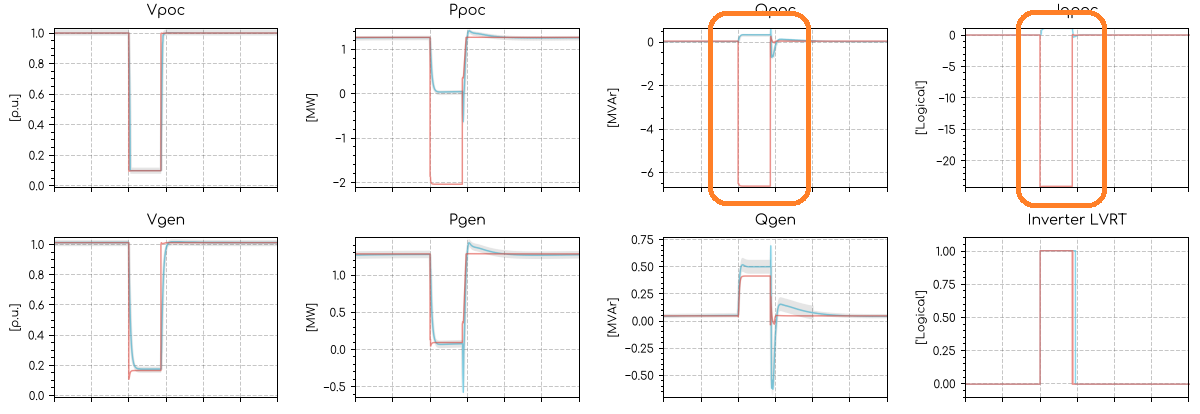
Fault tests or transient over voltage tests have massive reactive power spikes
If you see a result similar to the image below, where PSS®E has a large reactive power spike in seemingly the opposite direction to expected, consider checking the definition of the connection point bus in your Global Variables, Scenario Variables or your SIMPLEFAULT Command. It is possible you are applying a fault on the generator side of the connection point, therefore seeing the fault contribution from the infinite bus in your plots.
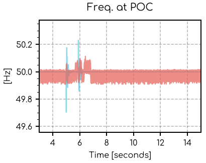
Very noisy frequency signal
If you see a result similar to the image below, where PSS®E has a very noisy frequency signal, this can be caused by the infinite bus generator having a series reactance which is too low.
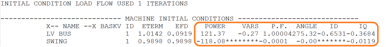
If you review the PSS®E log file (if rerun with logging enabled) you might see something similar to the image below. The asterisks mean the initial reactive power supplied by the infinite generator is so large it cannot be displayed. Increasing the infinite generator series reactance may help stabilise the PSS®E case.
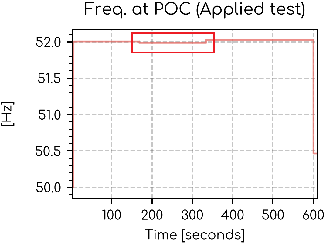
Unintended change in frequency of playback generator
We use the PLBVF1 model as the playback generator for SMIB studies. We've observed that during longer playback tests, the frequency may change slightly away from the specified playback response. This phenomenon is observed within the PSS®E software itself. The image below shows the observed response for a specified .plb file. This topic is observed
- .plb file
- Plot
0,      1,      50
5,      1,      50
5.5,    1,      52
600,    1,      52
600.125,1,      50.5
PSCAD™
Active power is constantly zero
Some PSCAD™ inverter models, especially for solar farms, only correctly initialise if the terminal voltage of the inverter is within acceptable limits within the first few seconds of the PSCAD™ simulation.
When completing tests at maximum power and maximum (or minimum) reactive power, the initial terminal voltage of the inverter may be outside of the range for which it can correctly initialise after importing the infinite bus voltage from PSS®E.
This can be counter-acted by starting at a terminal voltage closer to 1, by applying an external grid voltage ramp for the first few seconds of the PSCAD simulation. For example, see the below. Use a higher voltage (like 20%, though it is SCR dependent) if Q is being absorbed by the generator and a lower voltage (like -20%, though it is SCR dependent) if Q is being injected by the generator.
0, 20%
2, 0%
Value: cannot be assigned error
This normally means you are trying to set a float (decimal, like 1.02) to an integer constant block in PSCAD™. The two bubbles have very similar colours: the blue bubble is a constant integer and the green bubble is a constant float.

Solar inverter model initial instability caused by low irradiance
Solar inverter models may not initialise properly if the irradiance is set lower than nominal during model initialisation. For example, if channel 5 in smiby is source energy (irradiance), consider using a CONTROL, CH=5, VAL=X Command with AT=2 instead of AT=0 to allow the inverter model to correctly initialise.
Strange performance during fault
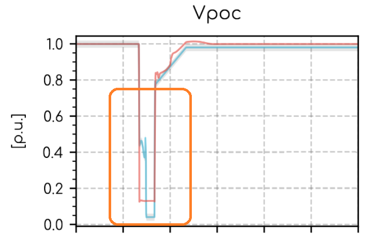
If you see a result similar to the image below, where PSCAD™ has a strange fault response, this can be caused by having too deep of a fault using the voltage playback. Generator models may be unstable if the voltage at the connection point drops below ~30% by use of the voltage playback (i.e. having a 5, 0.7 or 5, -30% line in the voltage playback). For deeper faults, consider using a SIMPLEFAULT, FZ=xx% Command.
Web App
There were errors in your simulation request. Please fix the errors listed and try again.
You may have tried to launch an invalid simulation.
Possible solutions:
- The Engine ID entered may be invalid. Please ensure your Engine ID is correct and your licence is valid.
- The Nodes and Edges in the Flow may not be configured properly. Please ensure you check all Nodes are connected properly.
The upload failed since the file was not a valid csv file. Please ensure the headers are correct.
This happens when you try to upload a Global Variables or Scenario Variables file which is not a valid .csv file. This may have been caused by manually editing the file using a text editor.
Possible solutions:
- Try opening the .csv in Microsoft Excel and then saving the file. Microsoft Excel will often force the file to be a valid .csv. Then try uploading the file again.
- Remove any additional columns you may have manually created.