Template: Energy Queensland Plant Energisation
Template version: v2
Country:

AU
Software required:
Source: Energy Queensland | STNW1179 - Standard for Plant Energisation | Version 3 | 21 February 2022

How to add this template to your project
- From within your gridmo project, open the flow dropdown and select 'Add flow'.
- Select the template you want to use and click 'Add to project'.

The example model provided with this template is illustrative only and may not be appropriate for your generating system. You should ensure that your model considers all required aspects including, but not limited to:
- The proposed mitigation strategies which are appropriate/feasible given the design of your generating system.
- Transformer specifications, including whether residual flux is specified. This is called "Remanent Flux" in PSCAD™.
Background
Energising large electrical equipment (e.g. transformers) on a power system can cause voltage dips and other transients . This may affect other nearby electricity customers or generators.
This template is used to complete a series of PSCAD™ simulations to evaluate the impact of plant energisation in line with Energy Queensland's requirements as per standard STNW1179.
Reference
Common assumptions
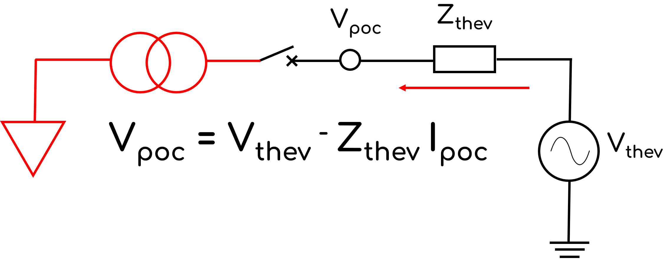
STNW1179 Section 5 Table 1 second requirement states, "The voltage returns to 95% of pre-disturbance rms voltage within 200ms". This requirement assumes that it is possible for the plant to return to the pre-disturbance value. However, this may not be possible depending on the plant configuration. Consider the example in the images below where the energisation of the plant causes a steady state change in Vpoc.

- STNW1179 Section 5 Table 1: The third requirement states that the acceptance criteria of plant energisation is that the energisation "must not cause existing or committed generating systems to enter fault ride through mode".
- There is generally insufficient information available to a connecting generator to identify how a nearby generator will respond to a transient disturbance without access to the PSCAD™ model of that generator, which typically cannot be provided due to confidentiality provisions.
- S5.2.5.5(g)(1) of the NER states that a generator must not commence a fault ride-through response if the voltage is between 0.90 p.u. to 1.10 p.u.
- Therefore, we assume that this requirement does not need to be assessed in this template, as it is covered by the first requirement in Table 1.
- STNW1179 Section 5 Table 1: The fourth requirement states that the acceptance criteria of plant energisation is that the energisation must "...comply with the allocated flicker limit".
- We note energisation is generally an infrequent occurrence. For example, Table 7 of AS/NZS 61000.3.7:2001 (as referenced in Section 6.5 of STNW1179) assumes each event is at least occurring once per hour.
- We assume that the energisation of the plant in question is happening significantly less often than once per hour and therefore it is occurring so irregularly that the 0.04 p.u. voltage flicker limit as per Table 7 of AS/NZS 61000.3.7:2001 is not applicable.
- STNW1179 Section 5.2:
- Requires the assessment to be completed at "system normal, minimum system strength and contingency (N-1) scenarios." We've assumed assessing the maximum and minimum system impedances (as per the gridmo Global Variables) is sufficient.
- References that "50 Hz voltage" needs to be reported. We've assumed that "50 Hz voltage" means instantaneous line to ground voltages on each phase.
- References the "minimum allowable pre-energisation voltage," however this term is not defined. We've assumed assessment is only required to be completed at the system normal voltage at the connection point (as per the gridmo Global Variable).
- Requires "period of time before the source voltage... to the pre-energisation voltage." We've assumed this is not applicable, as it’s likely that the post-energisation voltage will be lower than the pre-energisation voltage due to the reactive consumption of the plant under test (e.g. transformers).
- Requires "the RMS Percentage of Voltage over time from energisation of transformer to the time it takes to return within 1% of the pre-disturbance voltage." We've assumed that this will be achieved within 1 second and have configured all Plot Node's x-axis to end 1 second after the circuit breaker closes.
- We have assumed that a resolution of 0.5 ms is small enough to find the worst case plant energisation CB switching time.
- The plots in this template used for calculating settling time and minimum/maximum outputs display results only for the post‑snapshot signals and do not present the pre‑snapshot signals. A separate plot,
1025, shows both pre‑snapshot and post‑snapshot data aligned for comparison.
Sources
Revision history
Version 2 | 30 March 2026
Improvements- Initialisation from snapshot functionality added to improve simulation run speed.
Version 1 | 25 June 2025
- First release